4 external wiring – Yaskawa MEMOCON GL120 User Manual
Page 437
Installation and Wiring
— 5-80 —
5.4 External Wiring
This section explains the basic external wiring procedure for Digital I/O Modules. Refer
to the related manuals listed in on Table 5.15 in 5.3.4 Wiring Other Modules for the
external wiring procedures for other Modules.
External Wiring for Digital I/O Modules
1) Selection and Separation of Digital I/O Signal Cables
The digital I/O signal cable used for external wiring for Digital I/O Modules must be se-
lected according to the operating environment, including the mechanical strength, ef-
fects of electric noise, voltage used, etc. Use the table below to select and separate ap-
propriate I/O signal cables.
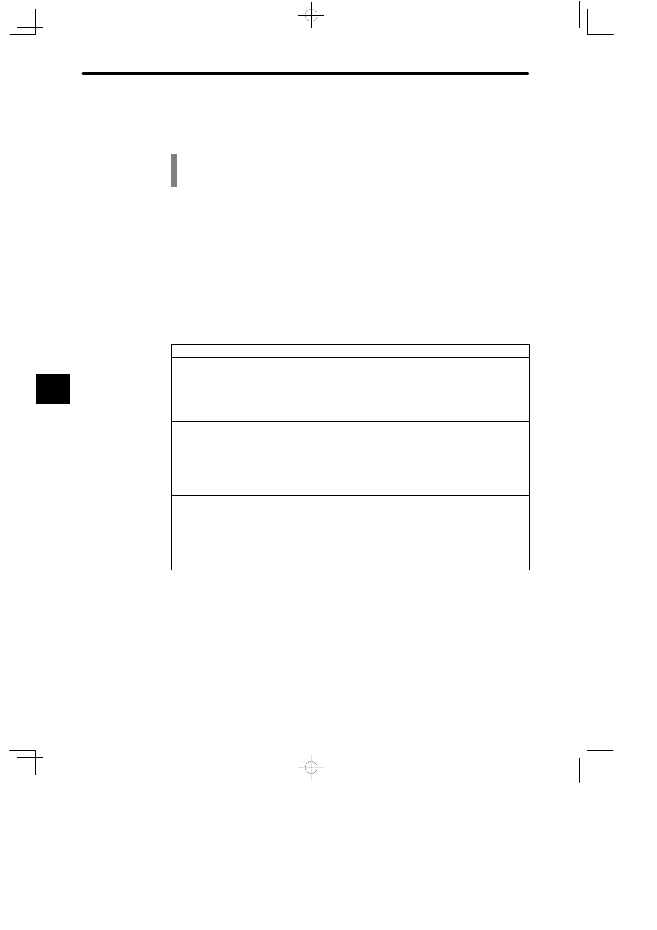
Table 5.19 Wiring Procedures for Digital I/O Signal Cables
Wiring Length
Procedures
30 m or less
1) A DC output signal line, a DC input signal line, an AC
output signal line, and an AC input signal line may be
housed in the same cable.
2) DC I/O signal lines and AC I/O signal lines must be
housed in separate cables.
30 to 300 m
1) Each DC output signal line, DC input signal line, AC
output signal line, and AC input signal line must be
housed in a separate cable.
2) If the induction voltage is large, attach either dummy
resistance, or use a separate fully shielded cable and
ground the shield on the GL120 or GL130 end.
300 m or longer
1) Considering the inrush current to Output Module, the
length of cable ought to be 300 m or less.
2) When the wiring length is more than 300 m, install a
junction relay in between so that the length between the
junction relay and the control panel is not more than
30 m.
2) Laying Digital I/O Signal Cables
I/O signal cables connected to Digital I/O Modules must be separated from general con-
trol circuit cables and power circuit cables as much as possible.
Leave 10 cm or more between digital I/O signal cables and a general control circuit
cables, and 20 cm or more between digital I/O signal cables and power circuit cables. If
separation is not possible, then use fully shielded cables, or as shown in the following
figure, take measures such as separating them by way of iron plate separators.
5