Yaskawa MEMOCON GL120 User Manual
Page 34
Overview
— 2-10 —
3) Up to two of each of the following Modules can be used for each GL120 or GL130 PLC.
D
Remote I/O Driver Module:
Mount to CPU Rack
D
PC Link Module:
Mount to CPU Rack
D
MEMOBUS Module (RS-232/RS-422):
Mount to any Rack of the local channel
D
4-axis Motion Module:
Mount to CPU Rack
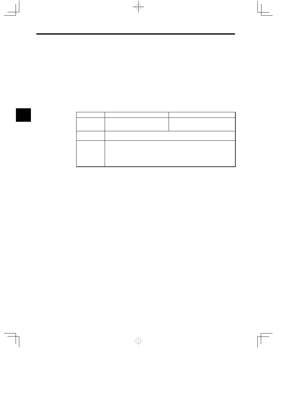
4) I/O Modules can be used within the maximum number of I/O points shown in the following
table.
Item
GL120 (CPU20, CPU21, CPU10)
GL130 (CPU30 and CPU35)
Number of
digital I/O
points
1,024 points max. (1 point = 1 bit)
4,096 points max. (1 point = 1 bit)
Number of I/O
registers
512 registers max. (1 register = 16 bits)
Number of
remote I/O
points
The number of I/O points and registers at each station must meet the following
conditions:
1) (No. of digital input points ÷ 8) + (No. of input registers x 2) ≤ 512 (bytes)
2) (No. of digital output points ÷ 8) + (No. of output registers x 2) ≤ 512 (bytes)
Figure 2.2 Outline of GL120,GL130 System Configuration (Continued)
2