A.1 panel layout – Yaskawa MEMOCON GL120 User Manual
Page 461
Advertising
Appendix A Examples of Panel Layout and Hole Dimensions
— A-2 —
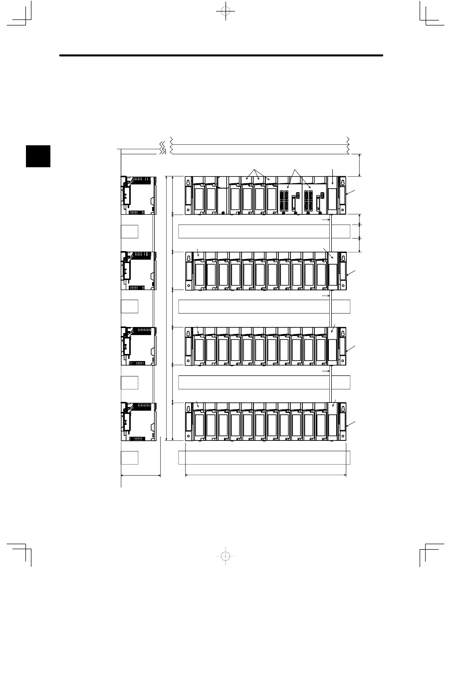
A.1 Panel Layout
Shown below is an example of a panel layout for the configuration components of the
GL120/GL130. (Unit: mm)
Ceiling board
Wire duct
Device or structure
Wire duct
Wire duct
Wire duct
Power
Supply
Module
Power Supply Module
Power Supply Module
Power Supply Module
CPU
Module
I/O Mod-
ules
4-axis motion
Modules
Expander
Module
Rack-to-rack I/O Cable
Rack-to-rack I/O Cable
Rack-to-rack I/O Cable
Expander Module
Expander Module
Expander Module
12-slot
Mounting
Base
12-slot
Mounting
Base
12-slot
Mounting
Base
12-slot
Mounting
Base
Device
mounting
steel
plate
80 min.
I/O Module
I/O Modules
I/O Module
W
D
130
130
130
130
130
130
130
910
50
50
30
A
Advertising
This manual is related to the following products: