Yaskawa MEMOCON GL120 User Manual
Page 432
5.3 Panel Wiring
— 5-75 —
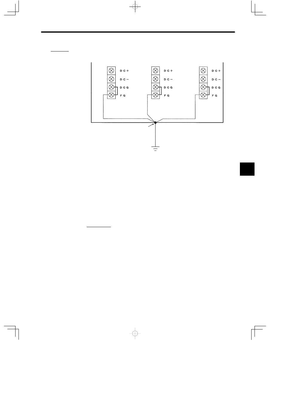
b) DC Power Supply Module
Field wiring terminal of
Power Supply Module
In-panel
ground cable
Control panel
Ground terminal (E)
Ground pole (with a resistance of
100 Ω max)
Field wiring terminal of
Power Supply Module
Field wiring terminal of
Power Supply Module
In-panel
ground cable
Outside-panel ground cable
In-panel
ground cable
B. Filter Ground Terminal (AC Modules: ACG; DC Modules: DCG)
This is the terminal for grounding the input line filter built inside the Power Supply Module.
This terminal is short-circuited with the protective ground terminal (FG) and a short piece
when the Module is shipped. In normal operation, use as it is.
Note
If current leaks from the filter ground terminal and this causes problems, remove the short
piece from between the filter ground terminal and the protective ground terminal. The input
line filter inside the Power Supply Module will be rendered ineffective. Make sure to insert
either a noise filter or an insulation transformer in the power supply circuit to the Power Supply
Module in order to increase noise resistance.
3. Grounding
A. Independent Ground
As a rule, the Modules forming the GL120 or GL130 should be grounded to an indepen-
dent ground pole at a ground resistance of 100 Ω or less.
B. Common Ground Pole
The Modules forming the GL120 or GL130 and devices related to general control circuits
can share a common ground pole. Do not, however, share the same ground pole be-
tween GL120/GL130 Modules and power devices.
C. Common Ground Line
The Modules Forming the GL120 or GL130 and devices related to general control circuits
cannot share a common outside-panel ground cable.
5
A
EXAMPLE
"