Yaskawa MEMOCON GL120 User Manual
Page 141
4.3 CPU Modules
— 4-85 —
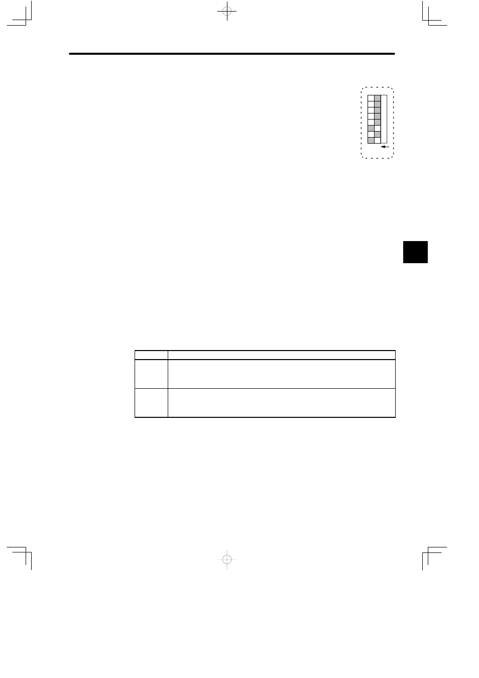
(2) Setting Pins 1 to 3
Set DIP switch pins 1 to 3 of the CPU21 of node 2 as shown in the
diagram at the right. Turning ON pin 3 sets the CPU21 of node 2 to
bridge mode. Turn ON pin 1 and turning OFF pin 2 sets the com-
munications parameters between personal computer and the
MEMOBUS port to the following settings:
Communications mode: RTU mode
Communications parameters:
Baud rate:
9,600 bps
Parity check:
Yes
Parity:
Even
Stop bits:
1
Data bit length: 8
Delay time:
0 ms
(3) The communications parameters of the RS-232C interface on the personal com-
puter must match the above values (except the delay time).
(4) A personal computer can run communications, via the CPU21 of node 2, with any
CPU Module (including the CPU21 of node 2) on the MEMOBUS PLUS network.
7) Setting Pin 5
Pin 5 is used to determine the start mode of the CPU Module. See the following table to
set this according for your system.
Table 4.28 Setting the Start Mode
Pin 5
Function
ON
1) Sets the start mode of the CPU Module to automatic RUN operation.
2) In this mode, the CPU Module will start in RUN mode when power is turned ON
to the CPU Rack.
OFF
1) Sets the start mode of the CPU Module to normal operation.
2) In this mode, the CPU Module will start in the mode it was in just before the
power supply was cut off (i.e., either RUN or STOP mode).
Note
The setting of pin 5 is effective (read) only when the AC power is turned ON to the Power
Supply Module of the CPU Rack.
8) Setting Pins 4 to 6
Pins 4 to 6 are used to determine whether or not a ROM operation is to be performed
when the CPU21 Module is turned ON. Set these pins according to the system require-
ments by referring to the following table.
4
1
234567
8
O N