Yaskawa MEMOCON GL120 User Manual
Page 173
4.4 Communications Modules
— 4-117 —
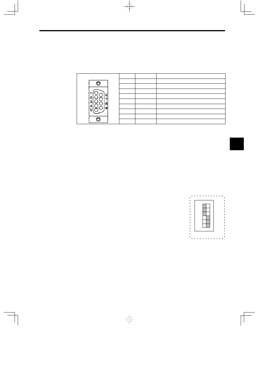
g) The connector for the MEMOBUS port is a D-sub connector (9-pin, female). The con-
nector pin arrangement and signal names are shown in the following table:
Table 4.48 Pin Arrangement and the Signal Names of MEMOBUS Port
Pin No.
Symbol
Signal Name
1
FG
Protective ground
2
TXD
Transmission data
3
RXD
Reception data
4
RTS
Request to send
5
CTS
Clear to send
6
DSR
Data set ready
7
GND
Signal ground
8
−
Not used
9
DTR
Data terminal ready
h) COM Instructions (COMM, COMR)
Note
(1) The COMR instruction can be used only for the MEMOBUS port of the Remote I/O Re-
ceiver Module.
(2) The COMM instruction cannot be used for the MEMOBUS port of the Remote I/O Re-
ceiver Module. The COMM instruction can be used for the MEMOBUS port of the fol-
lowing two communications Modules:
MEMOBUS Module (RS-232): Model JAMSC-120NOM26100
MEMOBUS Module (RS-422): Model JAMSC-120NOM27100
5) DIP Switch
a) The DIP switch is composed of 6 pins. The pins are num-
bered from 1 to 6 as shown in the diagram.
b) Each pin is turned ON when pressed it to the right.
c) Each pin becomes effective at the following times.
(1) Pins 2 to 4: When the pin setting is changed.
(2) Pin 1, pin 5, and pin 6: When the reset switch is pressed, or when power is turned
ON to the Power Supply Module of Rack 1 (Receiver Rack).
4
123456
1
6
SW
ON