Yaskawa MEMOCON GL120 User Manual
Page 129
4.3 CPU Modules
— 4-73 —
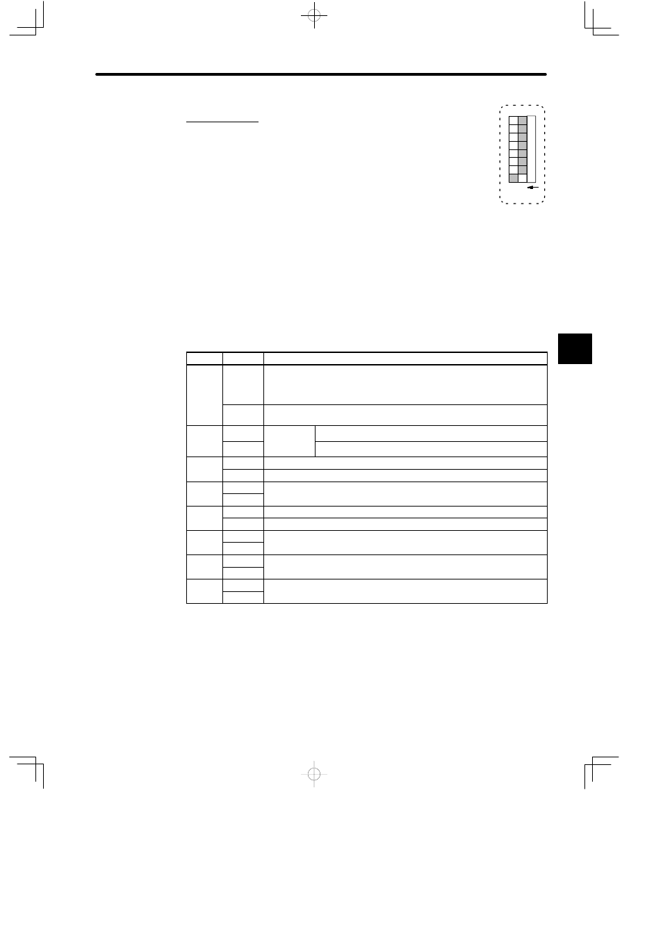
5. DIP Switch
1) The DIP switch consists of 8 pins. The pins are numbered from 1 to 8,
as shown in the diagram.
2) Each pin turns ON when it is moved to the left (toward the Key
switch).
3) Pins are effective at the following times:
a) Pins 1 to 3: Whenever the pin is turned ON.
b) Pin 5: When power is turned ON to the Power Supply Module on the CPU Rack.
4) Each pin’s function is shown in the following table. Refer to following pages for details.
Table 4.22 Function of DIP Switch Pins
Pin No.
Setting
Function
1
ON
1) Sets communications mode of MEMOBUS port according to the setting
of pin 2.
2) Sets communications parameter of MEMOBUS port to defaults.
OFF
Sets communications mode and parameters of MEMOBUS port to the user
settings.
2
ON
Effective
when pin 1
Sets communications mode of MEMOBUS port to ASCII.
OFF
when pin 1
is ON.
Sets communications mode of MEMOBUS port to RTU.
3
ON
Sets the CPU Module to bridge mode.
OFF
Release the CPU Module from bridge mode.
4
ON
For future use. It does not matter whether the pin is turned ON or OFF.
OFF
p
5
ON
Sets start mode of CPU Module to automatic RUN operation.
OFF
Sets start mode of CPU Module to normal operation.
6
ON
For future use. It does not matter whether the pin is turned ON or OFF.
OFF
p
7
ON
For future use. It does not matter whether the pin is turned ON or OFF.
OFF
p
8
ON
For future use. It does not matter whether the pin is turned ON or OFF.
OFF
p
4
1
234567
8
O N