Yaskawa MEMOCON GL120 User Manual
Page 174
System Components: Functions and Specifications
4.4.3 Remote I/O Receiver Module cont.
— 4-118 —
d) Each pin’s function is shown in the following table.
Table 4.49 Function of DIP Switch
Pin No.
Settings
Function
1
ON
Sets Module to self diagnosis mode.
OFF
Sets Module to remote mode.
2
ON
Sets MEMOBUS port to slave port. Master communications
becomes ineffective.
OFF
Sets MEMOBUS port to combined master/slave port. Master
communications becomes effective. When using COMR
instruction, turn OFF this pin.
3
ON
When using MEMOBUS port as master port, sets
communications mode to transparent mode.
OFF
When using MEMOBUS port as master port, sets
communications mode to MEMOBUS mode.
4
ON
When using MEMOBUS port as slave port, sets communications
mode and parameters to the defaults.
OFF
When using MEMOBUS port as slave port, sets communications
mode and parameters to user settings.
5
Sets the baud rate of the
R
I/O S
h
Pin 5
Pin 6
Baud rate
6
Remote I/O System as shown
at the right
ON
ON
4 Mbps
6
at the right.
ON
OFF
2 Mbps
OFF
ON
1 Mbps
OFF
OFF
0.5 Mbps
e) The default communications mode and parameters are as follows:
(1) Communications mode: RTU mode
(2) Communications parameters:
Baud rate:
9,600 bps
Parity check:
Yes
Parity:
Even
Stop bits:
1
Data bit length:
8
Delay time:
0 ms
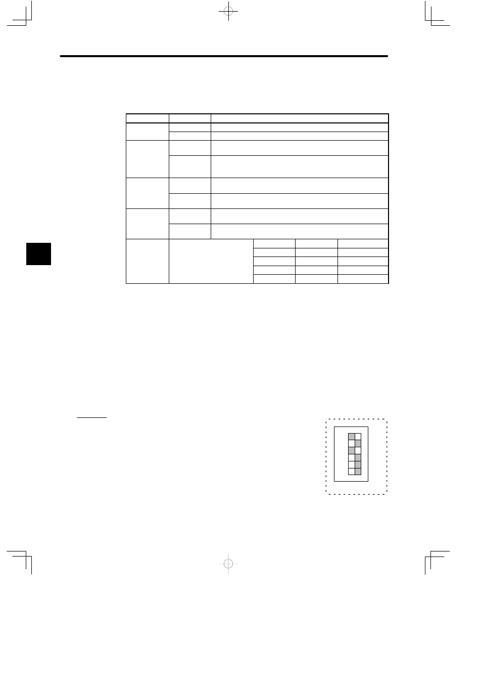
f) Examples of setting the DIP switch are shown below:
Example 1
When the DIP switch is set as shown in the diagram on the right,
the Remote I/O Receiver Module is set as follows:
• Module in remote mode.
• MEMOBUS port is used as slave port.
• When MEMOBUS port is used as slave port, communications
mode and parameters are set to the defaults.
• Baud rate of Remote I/O System is 4 Mbps.
4
A
EXAMPLE
"
123456
1
6
SW
ON