237 — 4. using high-speed counter modules – Yaskawa MEMOCON GL120 User Manual
Page 293
4.6 Special Purpose Modules
— 4-237 —
4. Using High-speed Counter Modules
1) Number of Modules
a) The following I/O references are necessary in the CPU Module for each High-speed
Counter Module.
• 16 consecutive input relays
• 16 consecutive output coils
• 4 consecutive input registers
• 4 consecutive output registers
b) Therefore, the number of High-speed Counter Modules that can be used is deter-
mined by how many of the above I/O references are available in the CPU Module.
2) Installation Locations
a) A High-speed Counter Module can be mounted to any slot of the Mounting Base of
any Rack. It will occupy on slot.
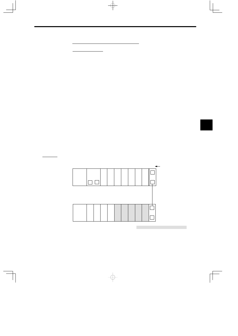
b) The following diagram shows where to mount a High-speed Counter Module.
PS10:
Power Supply Module (7 A)
CPU30:
CPU Module (32 KW)
DI:
12/24-VDC 16-point Input Module
DO:
12/24-VDC 16-point Output Module
CTR:
High-speed Counter Module
EXP:
Expander Module
MB12:
12-slot Mounting Base
W0100-02:Rack-to-rack I/O Cable (0.2 m)
DI
EXP
PS10
EXP
PS10
DI
DI
M
P
MB12
Slot No.
W0100-02
Rack 2
Rack 1 (CPU Rack)
DO DO DO DO CTR CTR CTR CTR CTR
MB12
CPU30
1
2
3
4
5
6
7
8
9
10
11
12
1
2
3
4
5
6
7
8
9
10
11
12
DI
DI
DI
DI
Local channel
Figure 4.70 Mounting High-speed Counter Modules
4
A
EXAMPLE
"