Yaskawa MEMOCON GL120 User Manual
Page 234
System Components: Functions and Specifications
4.4.10 Distributed I/O Driver Module cont.
— 4-178 —
Output references:
Digital output points + register output points ≤ 512 points
(One register is 16 points)
c) The number of Distributed I/O Driver Modules that can be used depends on the num-
ber of the above I/O references that can be allocated by the CPU module.
2) Installation Locations
a) A Distributed I/O Driver Module can be mounted to any slot on any rack on the Mount-
ing Base of the local channel. It will occupy 1 slot of the rack.
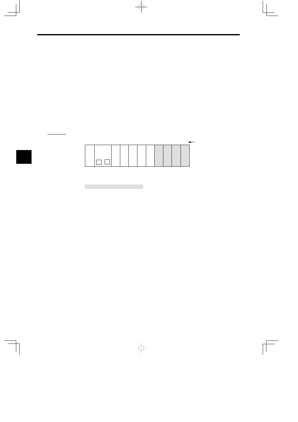
b) The following diagram shows where to mount a Distributed I/O Driver Module.
Example
PS05:
Power Supply Module (3 A)
CPU20:
CPU Module (16 KW)
VIOD:
Distributed I/O Driver
DI:
12/24-VDC 16-point Input Module
DO:
12/24-VDC 16-point Output Module
MB12:
12-slot Mounting Base
DI
VIO
D
PS
05
DO
DI
M
P
MB12
Slot No.
Rack 1 (CPU Rack)
CPU20
1
2
3
4
5
6
7
8
9
10
11
12
VIO
D
VIO
D
VIO
D
DO
Local channel
DI
Figure 4.50 Mounting Distributed I/O Driver Modules
4
A
EXAMPLE
"