Yaskawa MEMOCON GL120 User Manual
Page 199
4.4 Communications Modules
— 4-143 —
e) Transmission Circuit
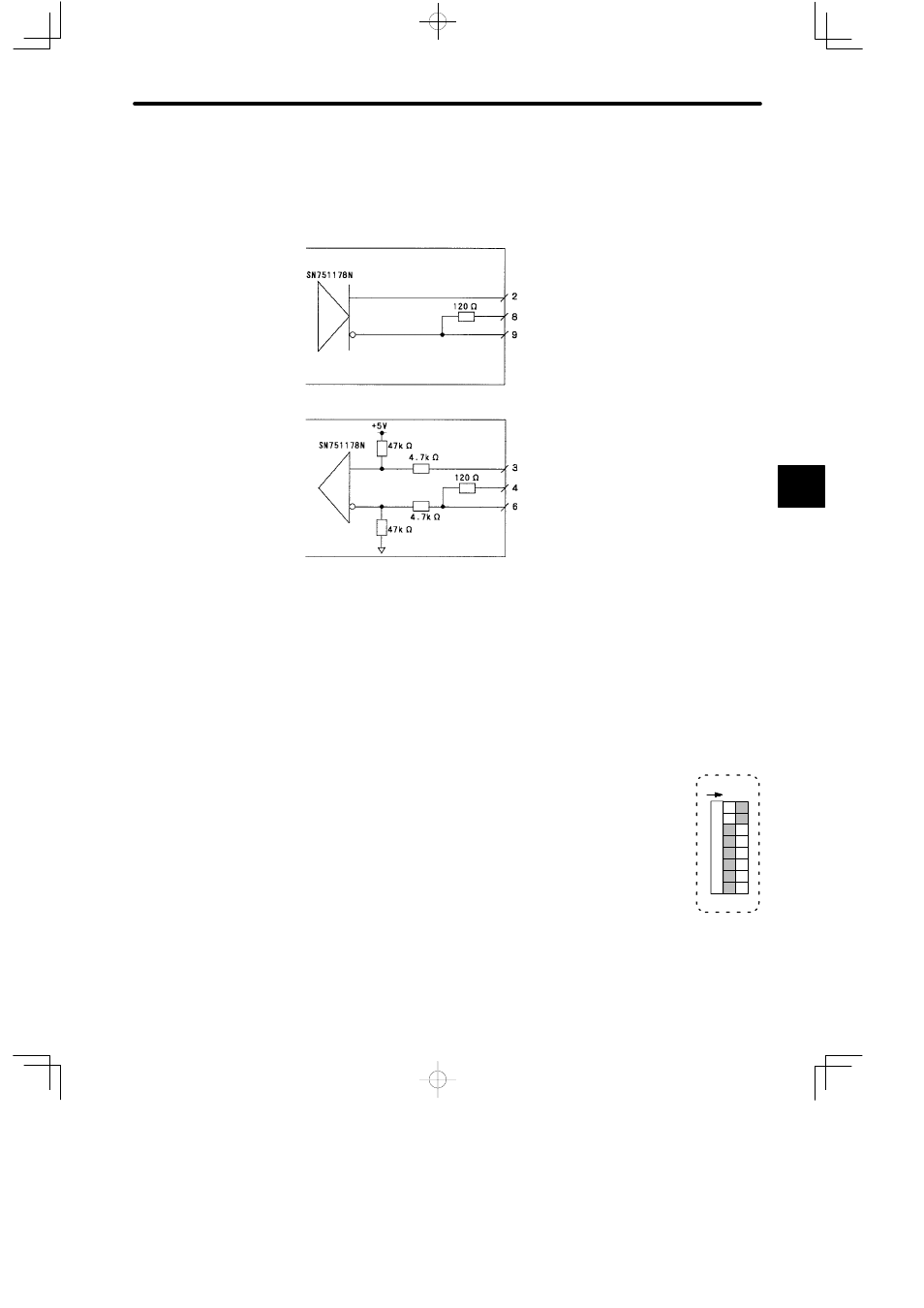
The communications circuits of the MEMOBUS Module (RS-422) are shown in the
following figure.
Transmission circuit
Reception circuit
Figure 4.37 Transmission Circuit of MEMOBUS Port
f) COM Instructions (COMM, COMR)
Note
(1) The communications instruction for the MEMOBUS ports of MEMOBUS Modules
(RS-422) is the COMM instruction.
(2) The COMR instruction cannot be used for the MEMOBUS ports of MEMOBUS Mod-
ules (RS-422). This communications instruction can be used only for the MEMOBUS
ports of the Remote I/O Receiver Module.
4) DIP Switch
a) DIP switch is composed of 8 pins. The pins are numbered from 1
to 8 as shown in the diagram at the right.
b) Each pin is turned ON when pressed to the right.
c) The setting of each pin is effective (read) at the following times:
(1) Pin 1 to 6: When the pin is turned ON.
(2) Pins 7 and 8: When the reset switch is pressed or when the power is turned ON to
the Power Supply Module of the Rack where the MEMOBUS Module (RS-422) is
mounted.
4
12345
678
O
N