Yaskawa MEMOCON GL120 User Manual
Page 165
4.4 Communications Modules
— 4-109 —
4) DIP Switch
a) The DIP switch consists of 6 pins. The pins are numbered
from 1 to 6 as shown in the diagram.
b) Each pin is turned ON when pressed to the right.
c) The setting of each pin is effective when power is turned
ON to Rack 1 (CPU Rack).
d) Each pin’s function is shown in the following table.
Table 4.45 Function of DIP Switch
Pin No.
Settings
Function
1
ON
Sets Module to self diagnosis mode.
OFF
Sets Module to remote mode.
2
ON
For future use
OFF
Sets Module to 120 I/O mode.
3
ON
Sets Module to master station of channel 2.
OFF
Sets Module to master station of channel 1.
4
ON
Not used. Set this pin to OFF.
OFF
p
5
Set the baud rate of Remote
I/O S
di
h
Pin 5
Pin 6
Baud rate
6
I/O System according to the
table shown on the right
ON
ON
4 Mbps
6
table shown on the right.
ON
OFF
2 Mbps
OFF
ON
1 Mbps
OFF
OFF
0.5 Mbps
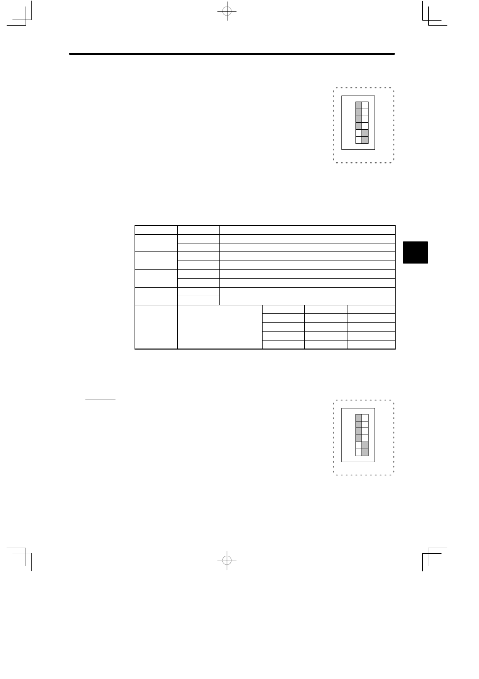
e) Examples of setting the DIP switch are shown below:
Example 1
When the DIP switch is set as shown in the diagram on the right,
the Remote I/O Driver Module is set as follows:
• Remote mode
• 120 I/O mode
• Master station of channel 1
• Baud rate: 4 Mbps
4
123456
1
6
SW
ON
A
EXAMPLE
"
123456
1
6
SW
ON