Yaskawa MEMOCON GL120 User Manual
Page 229
4.4 Communications Modules
— 4-173 —
5) DIP Switch
a) The DIP switch is composed of 4 pins. The pins are num-
bered from 1 to 4 as shown in the diagram at the right.
b) Each pin is turned ON when pressed to the left.
c) Each pin is effective (read) at the following timings:
(1) When the reset switch is pressed.
(2) When power is turned ON to the Power Supply Module of the Rack to which the
Uniwire (H) I/F is mounted.
d) Each pin’s function is shown in the table below.
Table 4.72 Function of DIP Switch
Pin
No.
Settings
Function
4
OFF
Reserved for manufacturer’s testing purposes. Always set this pin to OFF.
3
OFF
Use prohibited. Always set this pin to OFF.
2
Set the mode of the
U i i (H) I/F
di
Pin 2
Pin 1
Mode
1
Uniwire (H) I/F according
to the table on the right.
OFF
ON
Sets Module to 200-m mode.
Transmission distance: 200 m max.
The baud rate depends on the
combination of the transmission distance
mode and the interface mode.
Baud rate: H-System
29.4 kbps
Normal System 28.5 kbps
ON
OFF
Sets Module to 500-m mode.
Transmission distance: 500 m max.
The baud rate depends on the
combination of the transmission distance
mode and the interface mode.
Baud rate: H-System
14.7 kbps
Normal Sywtem 14.3 kbps
Note
(1) Never set both pins 1 and 2 simultaneously to ON or simultaneously to OFF. If you set
both pins either to ON or OFF by mistake, it will cause a pin setting error.
(2) Always leave pins 3 and 4 set to OFF. Setting these pins to ON by mistake may result in
incorrect outputs.
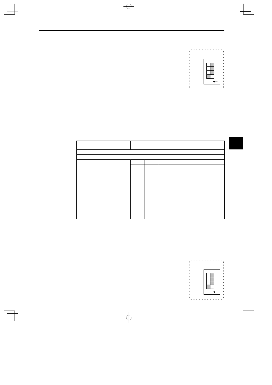
An example of setting the DIP switch
Example
Setting the DIP switch as shown in the diagram on the right, the
Uniwire (H) I/F is set to 200-m mode (baud rate: 29.4 or 28.5 kbps).
4
1234
TEST
−
L
H
O N
SPEED
A
EXAMPLE
"
1234
TEST
−
L
H
O N
SPEED