2 appearance of i/o modules – Yaskawa MEMOCON GL120 User Manual
Page 450
Low Voltage Directives
6.2.2 Appearance of I/O Modules
— 6-12 —
6.2.2 Appearance of I/O Modules
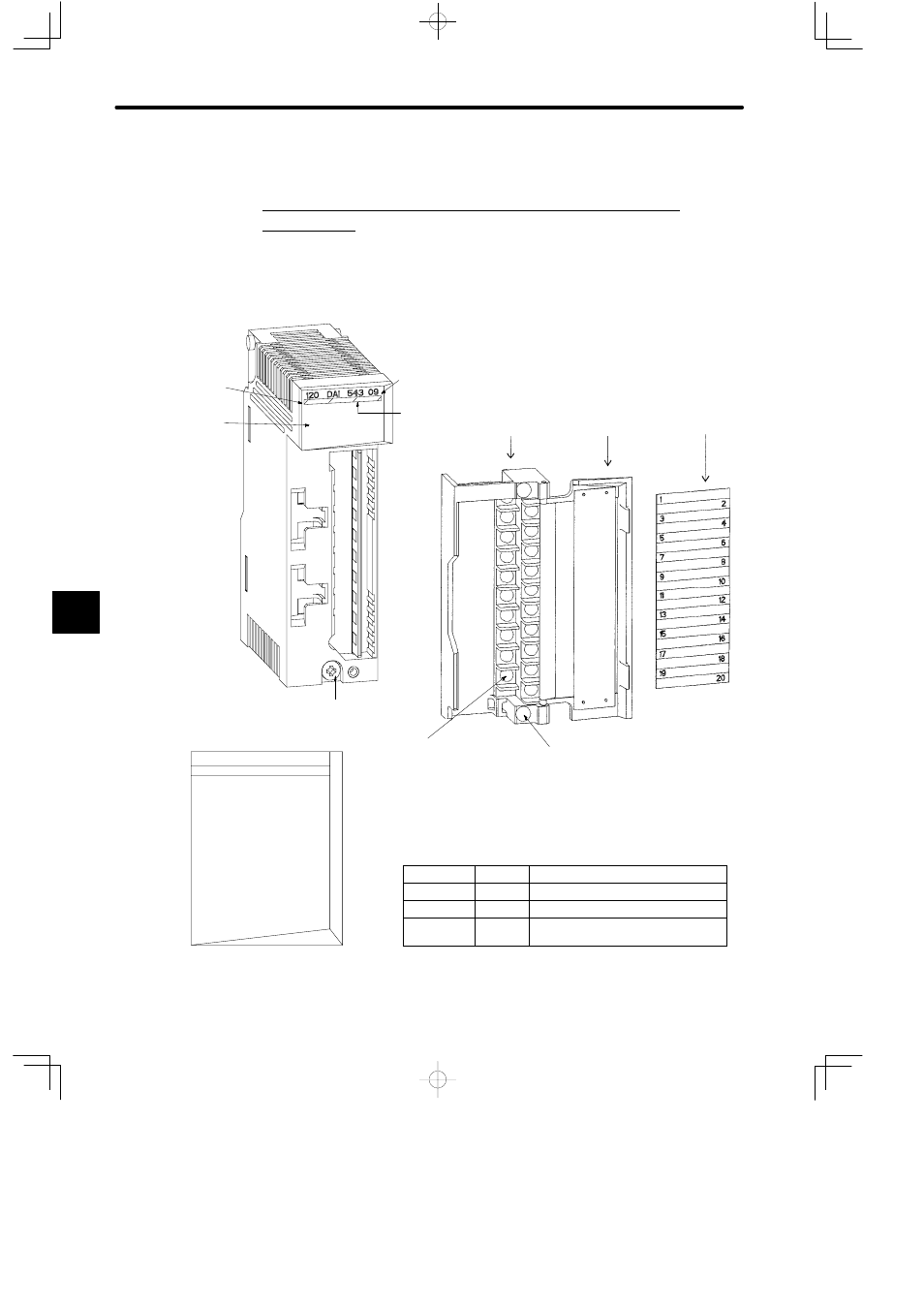
1. Appearance of I/O Modules with Terminal Blocks for Field
Connections
1) The following figure shows the appearance of Input Module:
100-to 120-VAC, 16-point Input Module (JAMSC-120DAI54309)
200-to 240-VAC, 16-point Input Module (JAMSC-120DAI74309)
Color code
(pink)
LED area
Removable
terminal block
for field
connections
Hinged
terminal cover
Signal label
inserts
Module description
(120DAI54309)
Module mounting screw
(Use M4 Phillips screwdriver)
Field wiring terminal
(Use M3 Phillips screwdriver.)
Terminal block mounting screw (Black)
(Use M3 Phillips screwdriver.)
Color code (pink)
LED
Color
Indication when ON
ACTIVE
Green
Processing input/output.
F
Red
Always not lit.
1 to 16
Green
The corresponding LED is lit when
the input signal is ON.
Figure 6.5 Appearance of 100-to 120-VAC 16-point Input Module
LED area
120 DAI 543 09
ACTIVE
1
2
3
4
5
6
7
8
F
9
10
11
12
13
14
15
16
6