74 — 2. grounding the power supply module – Yaskawa MEMOCON GL120 User Manual
Page 431
!
Installation and Wiring
5.3.5 Grounding cont.
— 5-74 —
2. Grounding the Power Supply Module
A. Protective Ground Terminal (FG)
Caution
Ground the protective ground terminal to the resistance of 100 Ω max.
Not grounding the protective ground terminal may result in electrical shock and malfunc-
tion.
1) Connect the protective ground terminal (FG) and the ground terminal of control panel (E)
with an electric cable (internal panel ground cable) of 1.5 mm
2
(AWG 16) to 2.5 mm
2
(AWG 13). M4 Phillips screws are used for the protective ground terminals.
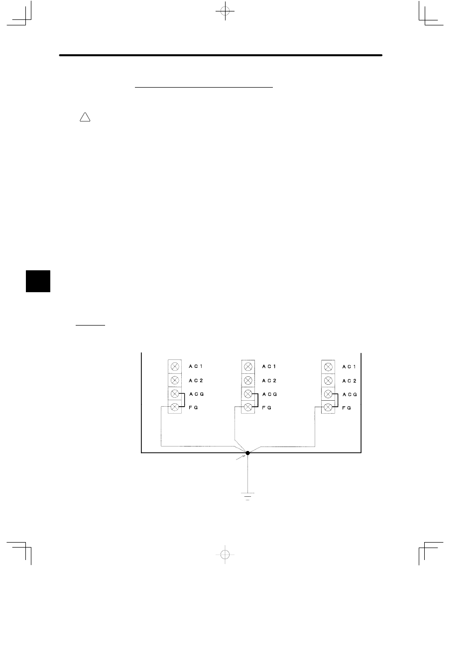
2) When more than one Power Supply Module is used, do not cross-wire between the pro-
tective ground terminals. Connect the protective ground terminal of each Power Supply
Module to the ground terminal of the control panel separately, as shown in the following
figure.
3) Connect the ground terminal of the control panel and the ground pole with a cable (out-
side-panel ground cable) of 8 mm
2
(AWG 8) or larger. Make sure that the length of this
ground cable is as short as possible.
4) Use a ground pole with a resistance of 100 Ω max. Do not use it together with the ground
cables or ground poles of high-voltage electrical devices.
a) AC Power Supply Module
Field wiring terminal of
Power Supply Module
In-panel
ground cable
Control panel
Ground terminal (E)
Ground pole (with a resistance of
100 Ω max)
Field wiring terminal of
Power Supply Module
Field wiring terminal of
Power Supply Module
In-panel
ground cable
(1.5mm
2
to 2.5 mm
2
)
In-panel
ground cable
Outside-panel ground cable
(8 mm
2
or larger)
5
A
EXAMPLE
"