4 using i/o modules – Yaskawa MEMOCON GL120 User Manual
Page 285
Advertising
4.5 I/O Modules
— 4-229 —
4.5.4 Using I/O Modules
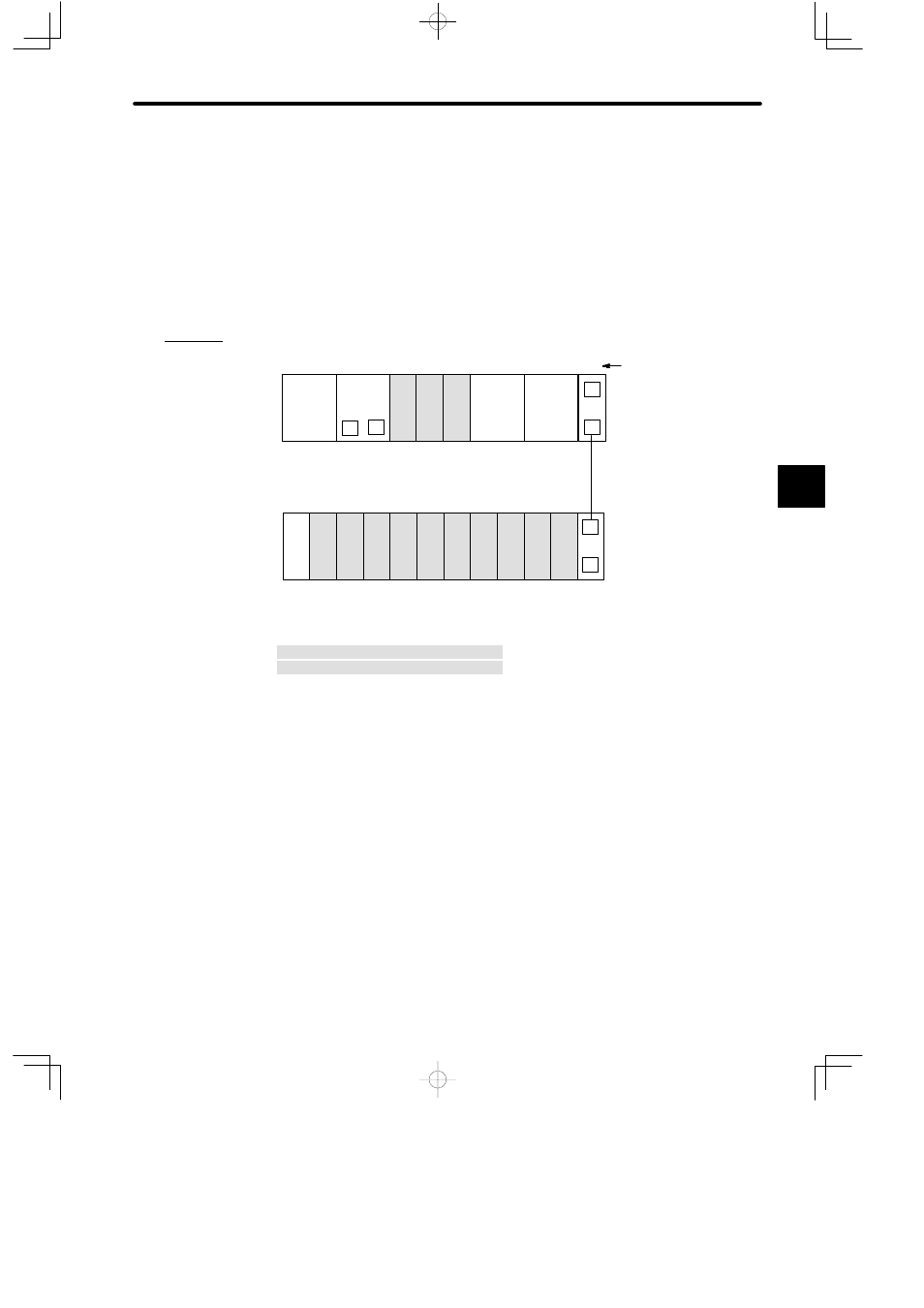
1) Installation Location of I/O Modules
a) I/O Modules can be mounted to any slot of the Mounting Base of any Rack. Each I/O
Module occupies one slot.
b) The following diagram shows an example on where to mount I/O Modules.
Example
PS10:
Power Supply Module (7 A)
PS05:
Power Supply Module (3 A)
CPU30:
CPU Module (32 KW)
DI:
12/24-VDC 16-point Input Module
DO:
12/24-VDC 16-point Output Module
MC20:
4-axis Motion Module
EXP:
Expander Module
MB12:
12-slot Mounting Base
W0100-02:Rack-to-rack I/O Cable (0.2 m)
DI
EXP
DI
PS
05
EXP
PS10
DO
DI
M
P
MB12
Slot No.
W0100-02
MC20
MC20
Rack 2
Rack 1 (CPU Rack)
DI
DI
DI
DI
DI
DO DO DO DO
MB12
CPU30
1
2
3
4
5
6
7
8
9
10
11
12
1
2
3
4
5
6
7
8
9
10
11
12
Figure 4.68 Example of Mounting I/O Modules
4
A
EXAMPLE
"
Advertising
This manual is related to the following products: