Yaskawa MEMOCON GL120 User Manual
Page 367
Advertising
!
Installation and Wiring
5.1.6 Mounting Base Layout cont.
— 5-10 —
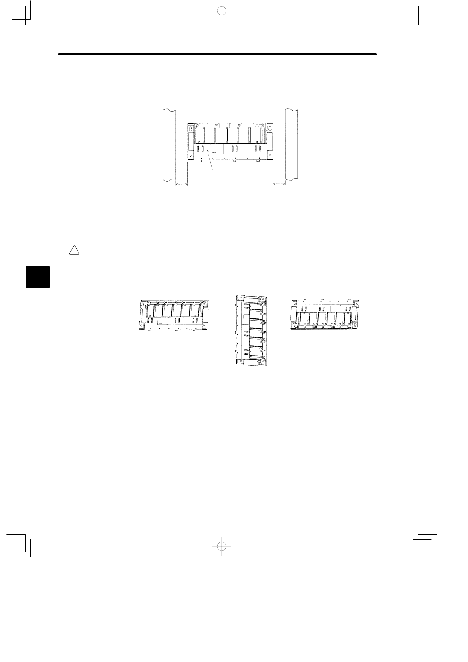
e) Provide sufficient space on both sides of a Mounting Base so that you can hold the
Mounting Base when installing or removing it.
Mounting Base
Wire
duct
Wire
duct
40 mm min.
40 mm min.
f) Always install a Mounting Base with its module hook facing upwards as shown in the
figure below.
WARNING
Mount the Mounting Base correctly. Incorrect installation may cause the Mounting Base to fall
off the wall, fail, or malfunction.
Module hook
CORRECT
WRONG
WRONG
2) Example of Mounting Base Layout
The following example shows four 12-slot Mounting Bases (MB12) mounted on a device
mounting steel plate. See A.2 Drilling Plan for the hole sizes for mounting a Mounting
Base on the device mounting steel plate.
5
Advertising
This manual is related to the following products: