Yaskawa MEMOCON GL120 User Manual
Page 251
4.4 Communications Modules
— 4-195 —
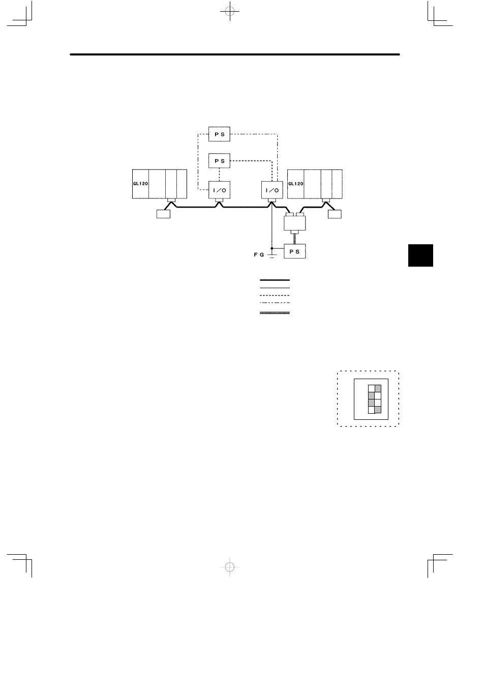
b) Slave Mode
The following illustration shows the system configuration when using the YENET
1600-D Module in Slave Mode.
Internal power supply for I/O
External power
supply for I/O
Terminating
resistance:
121 Ω
Communications power supply tap
(with reverse current prevention for
connection of multiple power supplies)
Communications power supply
Terminating
resistance:
121 Ω
Module
Master Mode
Trunk line
Branch line
External power supply line for I/O
Internal power supply line for I/O
Power supply line for communications
Slave Mode
Figure 4.59 System Configuration Example in Slave Mode
6) DIP Switch
a) DIP switch is composed of 4 pins. The pins are numbered
from 1 to 4 as shown in the diagram at the right.
b) Each pin is turned ON when pressed to the left.
c) The setting of each pin is effective (read) at the following
times:
(1) When the reset switch is pressed.
(2) When the power is turned ON to the Power Supply Module of the Rack where the
YENET 1600-D Module is mounted.
4
1234
4
1
SW
ON