Yaskawa MEMOCON GL120 User Manual
Page 409
!
Installation and Wiring
5.3.2 Wiring the Power Supply Module cont.
— 5-52 —
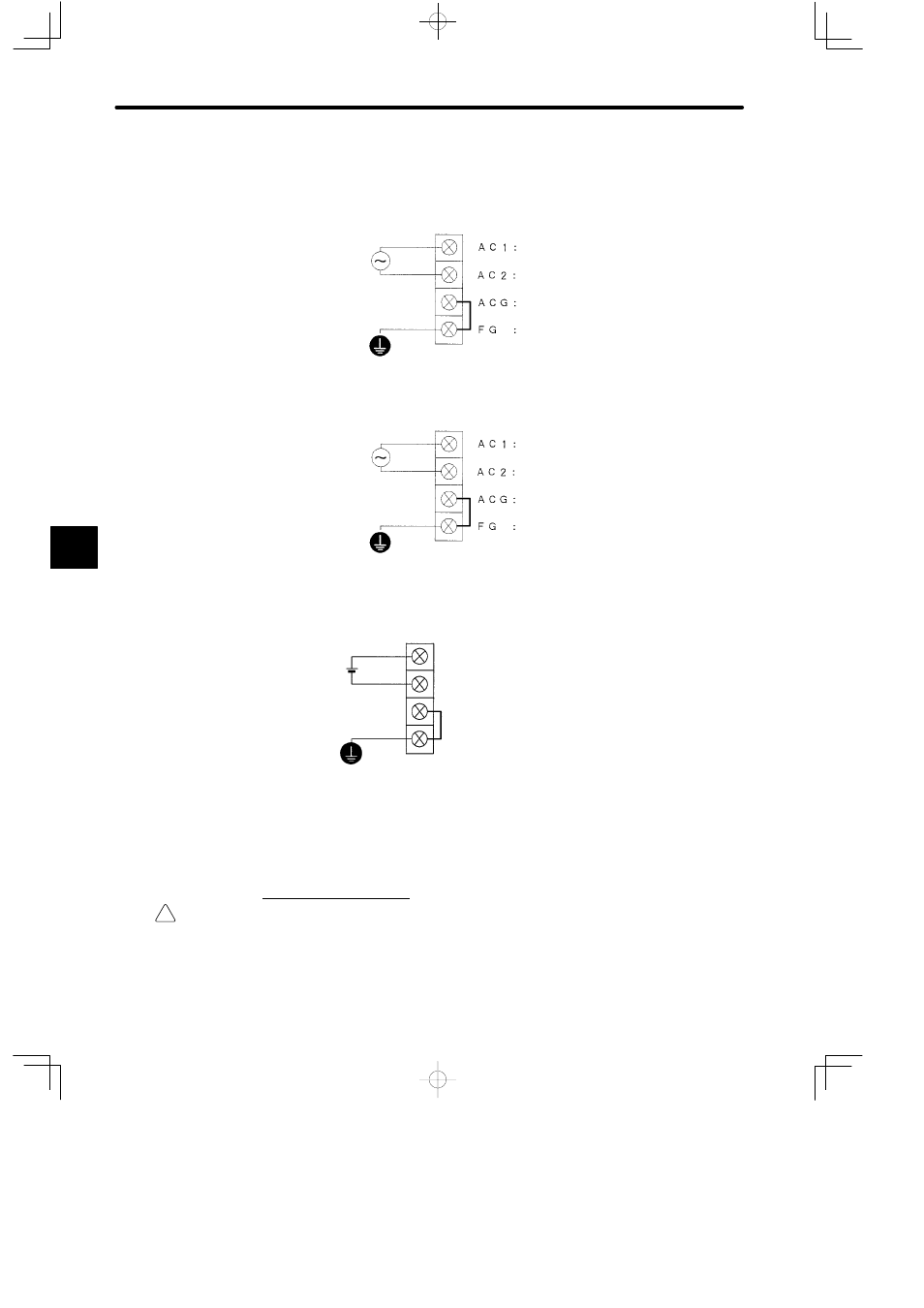
the AC Power Supply Module. The voltage that is supplied must be set on the input volt-
age selector switch.
a) When the input voltage selector switch is set to the top, supply 100 VAC as follows:
Supply single-phase,
85 to 132 VAC,
47 to 63 Hz.
Field wiring terminal 1
Field wiring terminal 2
Filter ground terminal
Protective ground terminal
b) When the input voltage selector switch is set to the bottom, supply 200 VAC as fol-
lows:
Supply single-phase,
170 to 264 VAC,
47 to 63 Hz.
Field wiring terminal 1
Field wiring terminal 2
Filter ground terminal
Protective ground terminal
2) DC Power Supply Modules
Supply DC power to the field wiring terminals (DC+, DC−) of the DC Power Supply Mod-
ule.
DCG: Filter ground terminal
FG: Protective ground terminal
DC−: Field wiring terminal 0 V
DC+: Field wiring terminal +24 V
Supply DC power:
20.4 to 28.8 VDC
Ripple: 1.0 V
p-p
3) Refer to Tables 4.3 to 4.6 in 4.2.3 Specifications of Power Supply Modules for details on
the input conditions for Power Supply Modules.
4) Use a low-noise AC power supply for AC Power Supply Modules. If noise is a problem,
use an insulation transformer or a noise filter.
2. Power Supply Cable
Caution
Do not accidentally leave foreign matter such as wire chips on the Mounting Base or in the
Module when wiring. This may cause fires, failures, and malfunctions.
1) Use power supply cable of 1.5 mm
2
(AWG 16) to 2.5 mm
2
(AWG 13) to connect field wir-
ing terminals, and always make sure to twist the wires together.
5