Yaskawa MEMOCON GL120 User Manual
Page 77
!
4.2 Power Supply Modules
— 4-21 —
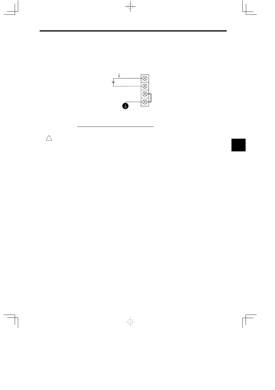
2) Use power supply wires of 1.5 mm
2
(AWG16) to 2.5 mm
2
(AWG13) to connect to the field
wiring terminals and make sure they are twisted. M4 Phillips screws are used on the ter-
minals.
FG: Protective ground terminal
DCG: Filter ground terminal
DC−: Field wiring terminal 0 V
DC+: Field wiring terminal +24 V
Power cables must be twisted.
5. Protective Ground Terminal (FG)
WARNING
Ground the protective ground terminal to a resistance of 100 Ω max.
Not grounding this terminal may result in serious electrical shock and/or malfunction.
1) Connect the protective ground terminal (FG) and the ground terminal of the control panel
with 1.5 mm
2
(AWG16) to 2.5 mm
2
(AWG13) wire (in-panel ground cable). M4 Phillips
screws are used on the protective ground terminal.
2) If more than one Power Supply Module is used, do not cross-wire between the protective
ground terminals. Connect the protective ground terminal of each Power Supply Module
to the ground terminal of the control panel separately, as shown in the following diagram.
3) Connect the ground terminal of the control panel to a ground pole with a wire (outside-
panel ground cable) of 8 mm
2
(AWG 8) or larger. Make sure that the length of this ground
cable is as short as possible.
4) Use a ground pole with a resistance of 100 Ω max. or higher. Do not use the same ground
cable and/or ground pole with other strong electrical equipment.
4