Yaskawa MEMOCON GL120 User Manual
Page 399
!
!
Installation and Wiring
5.2.6 Installing the Communications Modules cont.
— 5-42 —
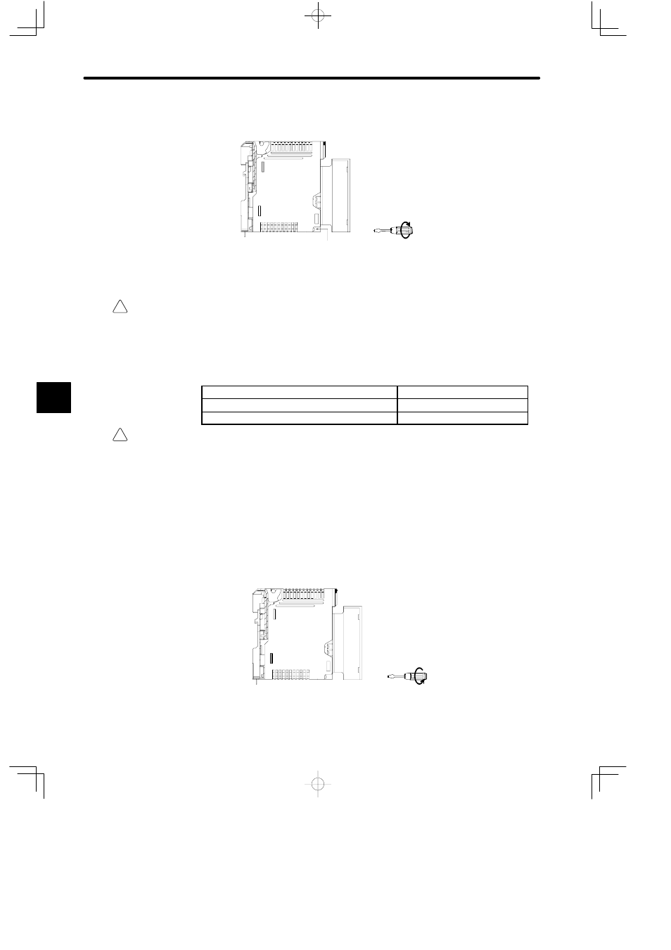
d) Tighten the Module mounting screw on the Module.
Module mounting screw
PCLINK
3) Removing modules
Caution
Always turn OFF the power to the Power Supply Module before removing the Modules that do
not support hot swapping.
Removing the Modules that do not support hot swapping while the power is being sup-
plied to the Power Supply Module may damage the Modules or cause a malfunction of
the GL120 and GL130.
Modules that Do Not Support Hot Swapping
Model No.
Remote I/O Driver Module
JAMSC-120CDR13100
2000-series Remote I/O Driver Module
JAMSC-120CDR13110
Caution
Always turn OFF the power to Power Supply Modules on the rack having the Ethernet I/F
Module Mounted, before removing the cables connected to the Ethernet I/F Module.
Removing cables connected to the Ethernet I/F Module while power is being supplied to
Power Supply Module may damage the Modules or cause malfunction of the GL120 and
GL130.
Use the following procedures to remove the Communications Module from the Mounting
Base.
a) Loosen the Module mounting screw on the PS10 Module.
Module mounting screw
(M4, Phillips)
PCLINK
5