Yaskawa MEMOCON GL120 User Manual
Page 263
4.4 Communications Modules
— 4-207 —
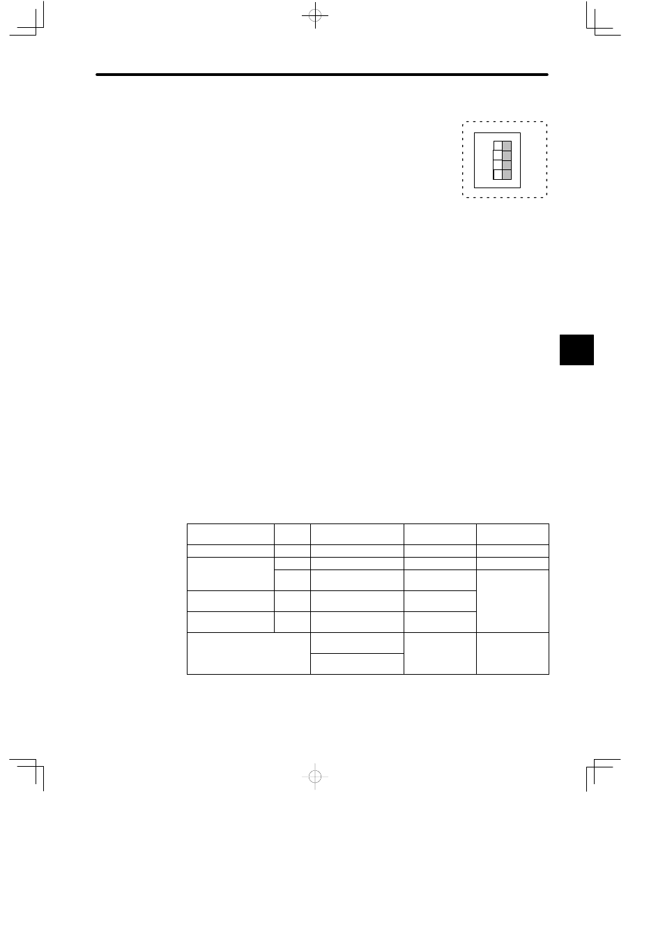
Example 2
When the DIP switch is set as shown in the diagram on the right,
the Ethernet Interface Module is set as follows:
• RUN mode
• 10Base-T
7) Reset Switch
a) Press the reset switch in the following cases:
(1) When you have changed the setting of the DIP switch.
(2) When you have changed the transmission parameters of the Module.
(3) When errors have occurred.
b) When the reset switch is pressed, communications between the Ethernet Interface
Module and other Ethernet Interface Modules are interrupted. Communications re-
start when the switch is released.
8) CPU Module and MEMOSOFT Versions Supporting Ethernet Interface Modules
a) The Ethernet Interface Module cannot be used with a CPU10 or CPU21.
b) The CPU Module and MEMOSOFT versions that are required to use an Ethernet In-
terface Module are shown in the following table.
Table 4.87 Versions Supporting Ethernet Interface Modules
Name
Model
Name
Model No.
Version Number
Location of
Version Number
CPU Module (8 KW)
CPU10
DDSCR-120CPU14200 Not supported.
---
CPU Module (16 KW) CPU21 DDSCR-120CPU34110 Not supported.
---
(
)
CPU20
DDSCR-120CPU34100 jj B09
onwards
Module
nameplate
CPU Module (32 KW) CPU30
DDSCR-130CPU54100 jj C03
onwards
a ep a e
CPU Module (40 KW) CPU35
DDSCR-130CPU54110 jj A04
onwards
MEMOSOFT
FMSGL-AT3 (for
English DOS)
1.41j onwards
In the middle at
the bottom of the
OSO
FMSGL-PP3E (for
P120 English version)
e bo o o
e
MEMOSOFT
startup screen.
Note
The nameplate is on the right side of the Module.
4
1234
1
4
SW
ON