3 pulse catch module, Appearance – Yaskawa MEMOCON GL120 User Manual
Page 295
Advertising
4.6 Special Purpose Modules
— 4-239 —
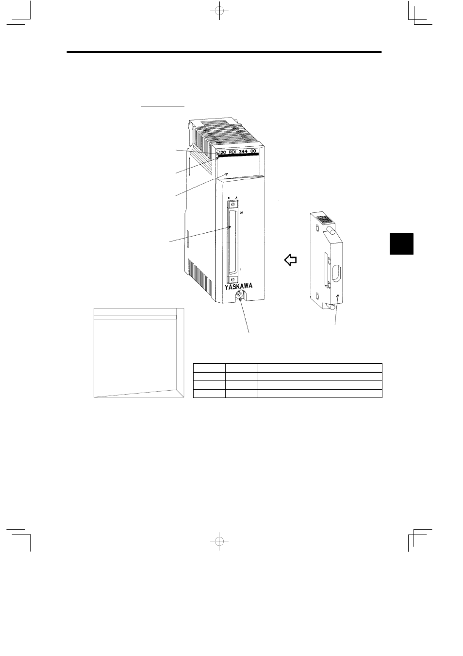
4.6.3 Pulse Catch Module
1. Appearance
Color code
(yellow)
LED area
Connector
Connector cover × 1 set
Model description
(120RDI34400)
Module mounting screw
(Use M4 Phillips screwdriver.)
LED
Color
Meaning When Lit
R
Green
Module is operating normally.
ACTIVE
Green
Module is being serviced by CPU Module.
1 to 16
Green
The corresponding input signal (1 to 16) is ON.
Figure 4.72 Appearance of Pulse Catch Module
4
LED Area
120 RDI 344 00
ACTIVE
R
1
2
3
5
6
7
8
4
9
10
11
13
14
15
16
12
Advertising
This manual is related to the following products: