Yaskawa MEMOCON GL120 User Manual
Page 243
4.4 Communications Modules
— 4-187 —
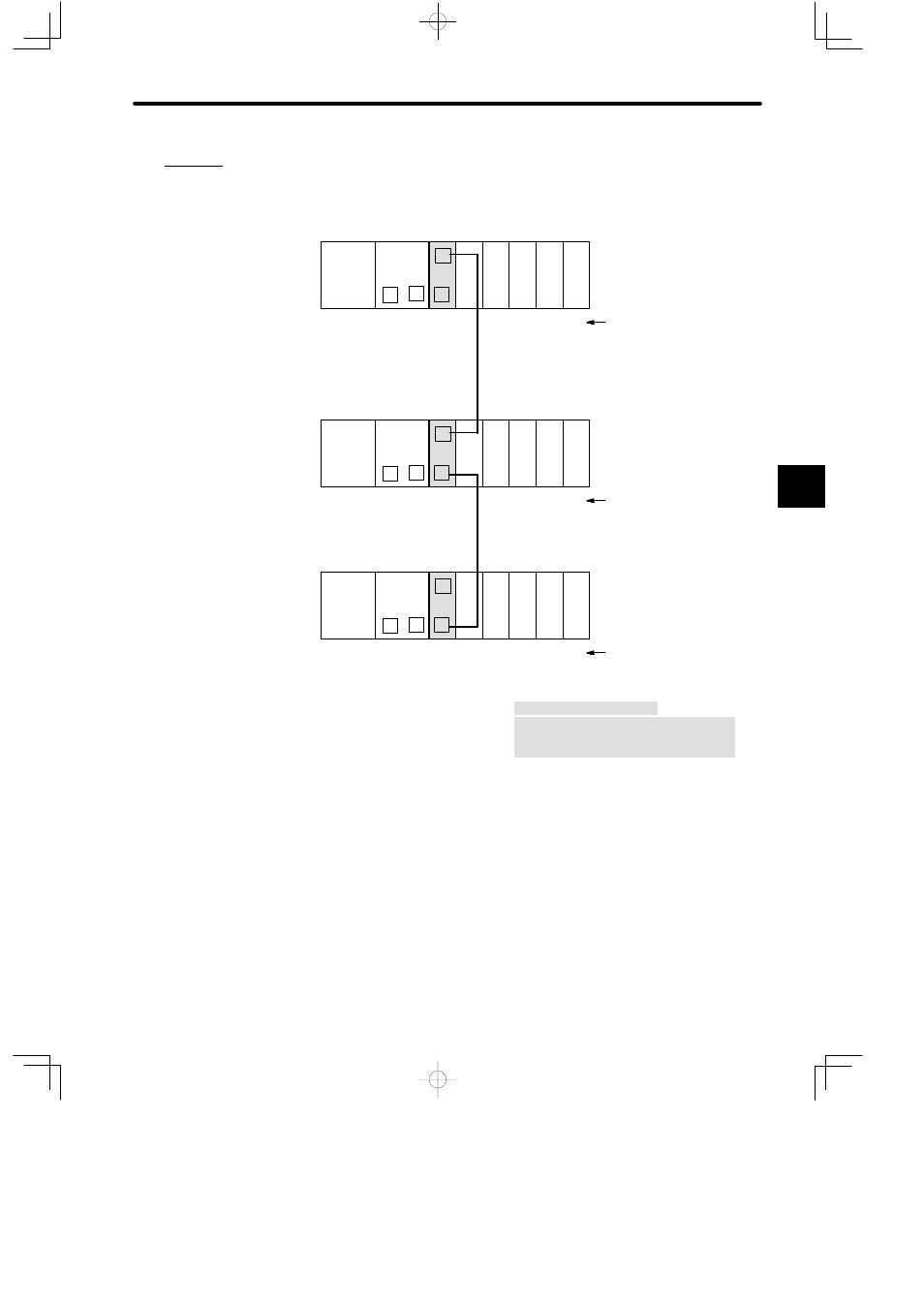
Example
Connection of M-NET Module
PS10:
Power Supply Module (7 A)
CPU20:
CPU Module (16 KW)
MB10:
10-slot Mounting Base
DI:
12/24-VDC 16-point Input Module
DO:
12/24-VDC 16-point Output Module
M-NET:
M-NET Module
M-NET Transmission Cable:
JKEV-SB 0.75 mm
2
x 2P (polyethylene-insu-
lated cable with copper braid shield)
M
DI
M-
NET
PS10
DI
DI
P
MB10
Slot No.
Rack 1 (CPU Rack)
CPU20
1
2
3
4
5
6
7
8
9
10
No.1 GL120
1
DO DO
M-NET Transmission Cable *1
2
M
DI
M-
NET
PS10
DI
DI
P
MB10
Slot No.
Rack 1 (CPU Rack)
CPU20
1
2
3
4
5
6
7
8
9
10
1
DO DO
2
M
DI
M-
NET
PS10
DI
DI
P
MB10
Slot No.
Rack 1 (CPU Rack)
CPU20
1
2
3
4
5
6
7
8
9
10
No.3 GL120
1
DO DO
2
M-NET Transmission Cable *1
No.2 GL120
Figure 4.54 Connection of M-NET Module
4) Related Manuals
Before operating your M-NET Module, read the following manual carefully and be sure
that you fully understand the information on specifications, applications methods, safety
precautions, etc.
MEMOCON GL120, GL130 M-NET Module User’s Manual (SIEZ-C825-70.12)
4
A
EXAMPLE
"