Yaskawa iQpump Controller Programming Manual User Manual
Page 142
142
YASKAWA
TM.iQp.07 iQpump Controller Programming Manual
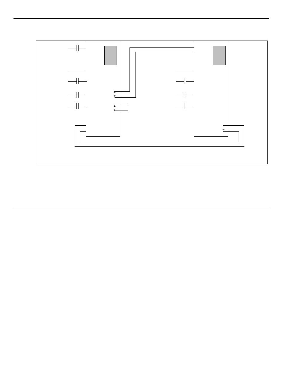
Figure 1.107
Figure 111.
Note: When the Fixed Speed Auto is activated, the sleep and lead-lag functions are disabled. This configuration is only active
in Auto Mode.
The L4-01 parameter of the last drive controls the previous drive and activates the Auto Mode (when the frequency level drops below
L4-01).
◆
MEMOBUS / Modbus Communication
<0034>
The current iQpump software only allows the drive to be a slave on a MEMOBUS / Modbus Network which means that an external
device such as a computer or PLC needs to be connected to the network and issue commands to the drives. Having a drive act as a
MEMOBUS / Modbus Master eliminates the need for an external master and introduces better drive control since it can be configured for
either a general or specific application feature.
iQ Pu mp
Run
S 1
Pressure Feedback
(H3-09 = B)
A 2 (4-20m A )
Pump Fault
(H1-01 = 24)
S 3 (H1-01)
Fault Reset
(H1-02 = 14)
S 4 (H1-02)
Set-Point Preset
(H1-03 = 80)
S 5 (H1-03)
Fixed Speed Auto
(H1-05 = 86)
S 7 (H1-05)
S N
M 1
M 2
(H2-01)
Digi tal
O utput 1
During Run 1
(H2-2 = 0)
i QP ump
S1
A 2 (4-20mA )
S3 (H1-01)
S4 (H1-02)
S5 (H1-03)
S7 (H1-05)
SN
Run
Pressure Feedback
(H3-09 = B )
Pump Fault
(H1-01 = 24)
Fault Reset
(H1-02 = 14)
Set-Point Preset
(H1-03 = 80)
M 1
M 2
M 3
M 4
P1-01 = 1 : Drive + 1 Pump
P1-01 = 0 : Drive only
H2-01 = 0 : During RUN 1
Figure 5.28
M 1
Pump 2 Control
(H2-01 = 40)
(H2-01 = 5)
L4-01 = Must be greater than P1-06
Frequency Detection 2
H2-01 = 5: Frequency Detection 2
L4-02 = 2.0 Hz