P1-13 hysteresis level, P1-14 prime loss level, Function description – Yaskawa iQpump Controller Programming Manual User Manual
Page 152
152
YASKAWA
TM.iQp.07 iQpump Controller Programming Manual
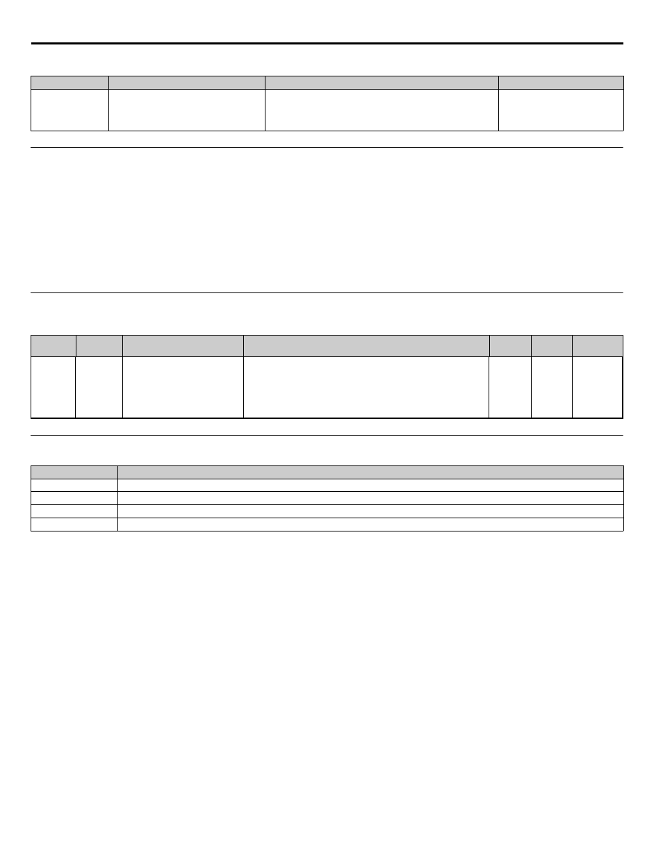
Table 57 Fault
<0034>
◆
P1-13 Hysteresis Level
Setting Range:
0.0 ~ 100.0
Factory Default: 0.0
The iQpump drive can be configured to detect Low Feedback Level (P1-07) and High Feedback Level (P1-09) alarms. The Hysteresis
Level (P1-13) is used to provide a bandwidth before the drive returns to normal operation. The Hysteresis Level is used to prevent rapid
cycling between alarm and normal operations.
The Hysteresis Level (P1-13) works in conjunction with the Low Feedback Level (P1-07) and High Feedback Level (P1-09) functions.
The units for this parameter are determined by the System Units (P1-02).
◆
P1-14 Prime Loss Level
Table 58 Parameters
◆
P1-15 Low / Hi Water Digital Input Congifuration / Water DI Config
<0034>
The iQpump drive can be configured to detect a low water level condition. To activate the low water level detection requires one of the
multi-function digital inputs to be programmed for low water level (H1-xx = 85). The multi-function digital input can be configured to
accept a normally closed or normally open contact by programming the Low Water Input (P1-15).
This function is only active during operation in the Auto Mode.
A digital input and fault may be added for “High Water Level” switch. A digital input was created to connect a float or pressure switch to
indicate if the level in the reservoir is too high. This fault will be detected whenever the drive is
Important: Refer to H1-xx = 85 on page
for further description of the low water level function.
■
Function Description:
<0034>
• The “High Feedback / High Water” will activate based on the PI feedback. However, this fault will also activate based on an digital
input (H1-0x = 88).
• The parameter that configures the Normally Open / Normally Closed operation of the Low Water switch has settings which will
configure the added High Water switch.
• The High Water condition will be detected anytime the drive is running.
• The High Water fault is NOT be auto-restartable.
Fault Display
Description
Cause
Countermeasures
NMS
Setpoint Not Met
Not Maintaining Setpoint
Setpoint cannot be maintained.
When the setpoint can not be maintained for a time specified in
P1-12. Function is disabled when the drive is not running and PID
is not active.
Possible causes:
Blocked Impeller, Over-Cycling, Broken Pipe
Difference between setpoint and
feedback is smaller than P1-11
Maximum Setpoint Difference.
Parameter
No.
Addr.
Hex
Parameter Name
Digital Operator Display
Description
Range
Default
Menu
Location
P1-14
0109
Prime Loss Level
Prime Loss Level
Used to detect loss of prime in the pump. If output current drops
below this level for the time specified in P1-12 and the output
frequency is at fmax, a “Loss Of Prime” fault occurs. The drive will
coast to a stop when a fault occurs.
If P1-01 = 3, the function is active on the lead drive, but will stop all
drives running on the network when the system fault occurs.
<0034>
0.0 ~
1000.0
0.0 A
Programming
Setting
Description
0
Low N.O. - Hi N.O. (Low Water Normally Open / High Water Normally Open)
1
Low N.C. - Hi N.O. (Low Water Normally Closed / High Normally Open)
2
Low N.O. - Hi N.C. (Low Water Normally Open / High Water Normally Closed)
3
Low N.C. - Hi N.C. (Low Water Normally Closed / High Normally Closed)