Figure 182, Event-based t ime, Drive detection – Yaskawa iQpump Controller Programming Manual User Manual
Page 246
246
YASKAWA
TM.iQp.07 iQpump Controller Programming Manual
Figure 1.178
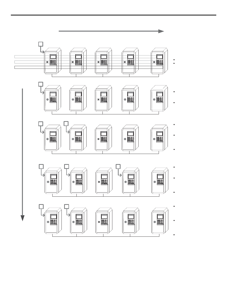
Figure 182. Multiplex Operation when P9-01 = 0 (Next Available) and P9-05 = 0 (Lag Fixed)
iQpump
Slave Address:
1
iQpump
4
iQpump
3
iQpump
2
10h
6h
8h
12h
Run Time Elapsed:
Running in Auto:
Off/Stopped/PI/Fixed:
iQpump
12h
5
Off
Off
Off
Off
Off
iQpump
iQpump
iQpump
iQpump
10h
6h
8h
12h
iQpump
12h
PID
Stopped
Off
Stopped
Stopped
1
x
Run Order / Pump#:
iQpump
iQpump
iQpump
iQpump
10h
6h
8h
12h
iQpump
12h
Fixed
PI
Off
Stopped
Stopped
1
2
iQpump
iQpump
iQpump
iQpump
10h
6h
8h
12h
iQpump
12h
Fixed
Fixed
Off
PI
Stopped
1
2
3
iQpump
iQpump
iQpump
iQpump
10h
6h
8h
12h
iQpump
12h
Fixed
PI
Off
Stopped
Stopped
1
2
Event-based
T
ime
Power-On
No Auto-Run Command
Auto-run Closed
Simultaneously for
Slaves 1, 2, 4, & 5
Master Runs First
Available Drive in PI
Feedback Level is too
low, and Pump 1
already maxed-out
Based on the Multiplex
parameters, Pump 1
requests for the NEXT
drive
Master Runs Pump 2 in
PI, and fixes the speed
of Pump 1.
Feedback Level is still
low, and Pump 2
already maxed-out
Based on the Multiplex
parameters, Pump 2
requests for the NEXT
drive
Master Runs Pump 3 in
PI, and fixes the speed
of Pump 2.
Feedback Level is too
high, and Pump 3
running at minimum
frequency
Based on the Multiplex
parameters, Pump 3
requests for the
PREVIOUS drive
Master Runs Pump 2 in
PI, and issues a
Baseblock on Pump 3.
Drive Detection