Yaskawa iQpump Controller Programming Manual User Manual
Page 15
YASKAWA TM.iQp.07 iQpump Controller Programming Manual
15
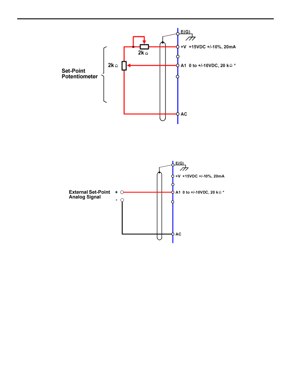
Figure 1.3
Figure 3. Setpoint Potentiometer Connection Diagram
Refer to
for the connection diagram for an external analog signal setpoint reference.
Note: When b1-01 = 1 (terminals) and P5-01 = 0 (hand mode reference source), the setpoint and the hand reference are
determined by the external analog signal.
Figure 1.4
Figure 4. External Analog Signal Setpoint Reference
Setting the iQpump drive to receive the “Auto Setpoint” from serial communication: Set b1-01 = “2: Serial Com,” and connect the
RS-485 / 422 serial communications cable to terminals R+, R-, S+, and S- on the control I/O terminal block.
Refer to
for the connection diagram using a PC to provide the auto setpoint reference to the iQpump drive. Further information
regarding communication protocols are referenced in
.