Drive 1 drive 2 drive 3, Drive 4 – Yaskawa iQpump Controller Programming Manual User Manual
Page 256
256
YASKAWA
TM.iQp.07 iQpump Controller Programming Manual
Figure 1.191
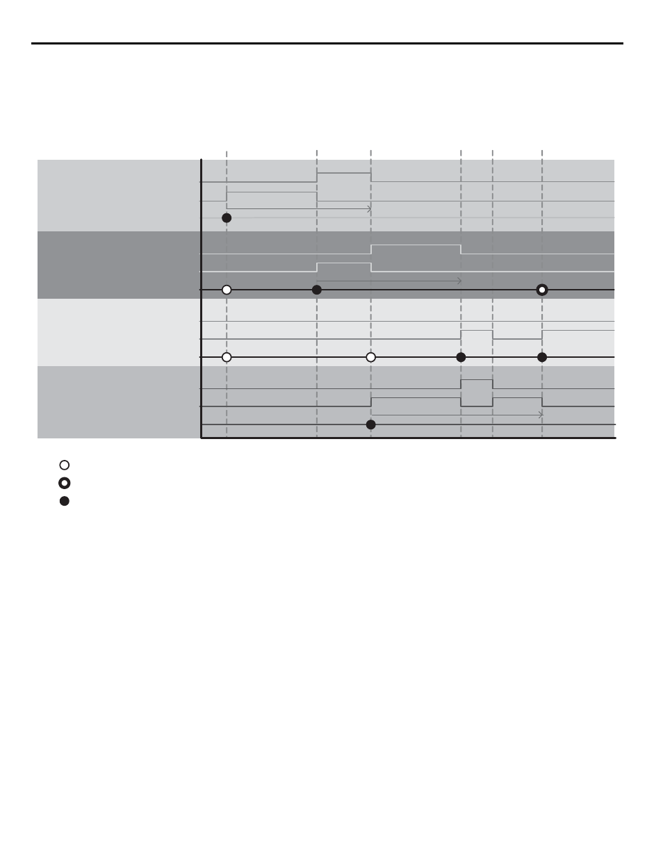
Figure 195. P9-01, P9-20 and P9-21 Interaction Example
PumpNet Control 1 U1-xx bit 1:
Run as Lag Drive
PumpNet Control 1 U1-xx bit 2:
Run as Lead Drive
PumpNet Control 1 U1-xx bit 1:
Run as Lag Drive
-
PumpNet Control 1 U1-xx bit 2:
Run as Lead Drive
PumpNet Control 1 U1-xx bit 1:
Run as Lag Drive
PumpNet Control 1 U1-xx bit 2:
Run as Lead Drive
Drive 1
Drive 2
Drive 3
PumpNet Control 1 U1-xx bit 1:
Run as Lag Drive
PumpNet Control 1 U1-xx bit 2:
Run as Lead Drive
Drive 4
Alternation Timer P
9-03
P9-20 = 2 (First Only)
P9-21 = 3
U1-13 = 18H
P9-20 = 0 (Always)
P 9-21 = 6
U1-13 = 7H
P9-20 = 1 (First/Alternation)
P9-21 = 6
U1-13 = 1H
P9-20 = 3 (Alternation Only)
P 9-21 = 3
U1-13 = 6H
Available to Act
Available to Act
Available with Priority
Available with Priority
Selected to Run
Selected to Run
Considered ?
Considered ?
Considered ?
Considered ?
Need more
pressure…
Drive 3 is
staged
Start -up…
Drive 4 is the
First Pump
Drive 4
alternation
timer is up…
Drive 1 is
forcibly
alternated as
Lead
Alternation Timer P9-03
Drive 3
alternation
timer is up…
Drive 2 is
forcibly
alternated
as Lead
Pressure is
high…
Drive 2 is
de-staged
Alternation Timer P
9
-
03
Drive 1 alternation
timer is up…
Drive 2 is forcibly
alternated as Lead
P9-01 = 1 (Lowest Run-time)
P9-04 = 1 (FIFO Forced)