Function: minor fault (setting: 10), Function: reset cmd active (setting: 11), Function: timer output (setting: 12) – Yaskawa iQpump Controller Programming Manual User Manual
Page 80: Function: reverse dir (setting: 1a)
80
YASKAWA
TM.iQp.07 iQpump Controller Programming Manual
■
Function: Minor Fault (Setting: 10)
A Minor Fault, also referred to as an alarm, indicates that a condition exists that may be critical to the iQpump drive or application but
does not require the iQpump drive to stop. A minor fault will be flashed on the digital operator but neither the Fault output (MA-MB) nor
any digital output configured as a Fault output (H2-0x = E) will close. Any digital output configured as Minor Fault will close whenever
a minor fault of alarm condition exists.
■
Function: Reset Cmd Active (Setting: 11)
A Reset Cmd Active digital output will close to signal that a Fault reset is being attempted from terminals or Serial Com.
■
Function: Timer Output (Setting: 12)
This Timer function, that is built into the drive, is independent of the rest of the iQpump drive operation, i.e. there is no requirement for a
Run command for the timer to operate. A Timer digital output will close b4-01 seconds after a digital input configured as Timer Input
(H1-0x = 18) closes and remains closed. The Timer digital output will remain closed for b4-02 seconds after the Timer digital input opens
and remains open.
Refer to the descriptions of parameters b4-01 and b4-02 for a timing chart of the Timer function.
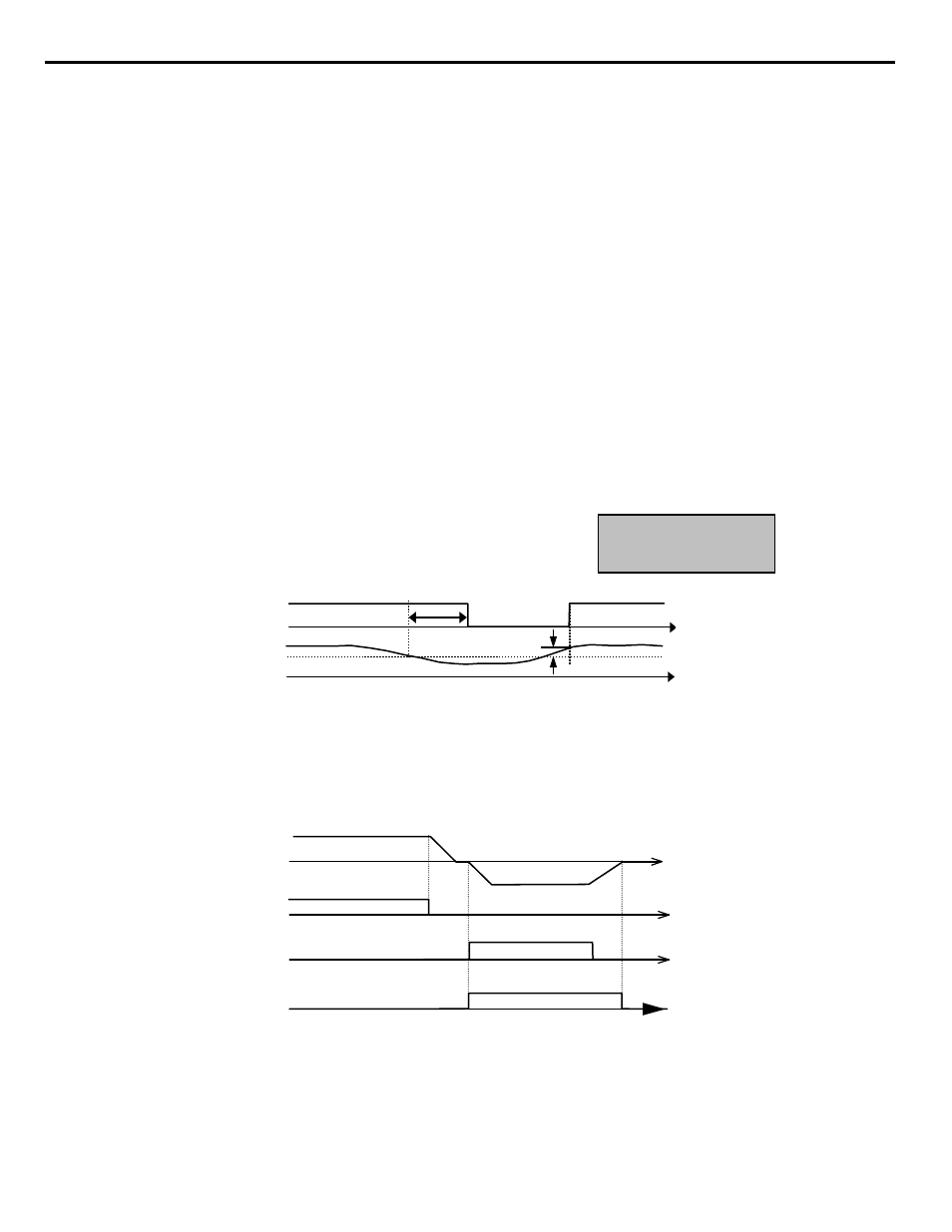
Function: Trq Det 1 N.C. (Setting: 17)
The Trq Det 1 function ties a digital output to the overtorque / undertorque sensing capabilities of the drive. If a digital output is
configured as Trq Det 1 N.C., whenever the output current exceeds the level of L6-02 for at least the length of time set in L6-03, the
digital output will open.
The torque detection function has a built-in hysteresis of 10% of the iQpump drive rated output current.
Figure 1.68
Figure 68. Trq Det 1 N.C. Timing Diagram
■
Function: Reverse Dir (Setting: 1A)
The Reverse Dir digital output will close whenever the iQpump drive is turning the motor in the direction that corresponds to the reverse
direction (CW or CCW). The Reverse Dir digital output will remain closed during deceleration when the rotation is in the reverse
direction.
Figure 1.69
Figure 69. Reverse Direction Timing Diagram
Undertorque Detection
Signal
t
L6-03
L6-02
t
Output Current
b
ON (Closed)
OFF (Open)
L6-01 = 5,6,7, or 8
L6-02 = TD Level 1
L6-03 = TD Delay Time 1
b = 10% of Drive rated current
TIME
Output Frequency
Fwd RUN
Rev RUN
Reverse Dir Output
ON (Closed)
ON (Closed)
ON (Closed)
OFF (Open)
OFF (Open)
t
OFF (Open)
Reverse Dir Output
TIME