Figure 5 – Yaskawa iQpump Controller Programming Manual User Manual
Page 16
16
YASKAWA
TM.iQp.07 iQpump Controller Programming Manual
Figure 1.5
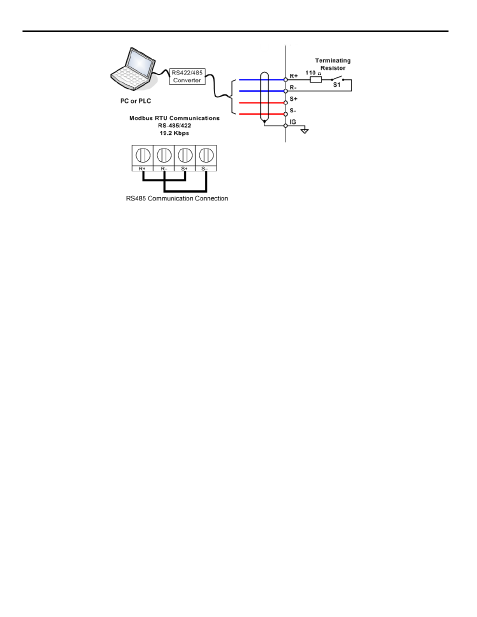
Figure 5. Connection Diagram of PC or PLC
To configure the iQpump drive to receive the “Auto Setpoint” for a network communication option card: Set b1-01= “3: Option
PCB,” and plug a network option board (p/n SI-J) into the 2CN port on the iQpump drive Control PCB. Consult the manual supplied with
the option board for instructions on integrating the iQpump drive into the network system.
The iQpump drive can support the following network communication options. Refer to the appropriate Installation Guide (IG) and
Technical Manual (TM) for further details. These network communications documents can be located at http://iQpump.yaskawa.com.
Important: If b1-01 = “3: Option PCB” but a network card is not installed in 2CN, an OPE05 Operator Programming Error will be
displayed on the digital operator and the iQpump drive will not run.
■
Start / Stop from Comm. Option Card (Parameter b1-01 = 3):
The iQpump Controller allows for the setpoint reference to be set via any of the following communication option cards:
Profibus DP Option Card CM061
Manual: IG.AFD.12
DeviceNet Option Card CM05X
Manual: IG.AFD.14
Modbus Plus Option Card CM071
Manual: IG.AFD.17
Modbus TCP/IP Option Card CM090
Manual: IG.AFD.25
EtherNet/IP Option Card CM092
Manual: IG.AFD.26
Profibus DP Option Card CM061
Manual: IG.AFD.12
DeviceNet Option Card CM05X
Manual: IG.AFD.14
Modbus Plus Option Card CM071
Manual: IG.AFD.17
Modbus TCP / IP Option Card CM090
Manual: IG.AFD.25
EtherNet / IP Option Card CM092
Manual: IG.AFD.26