Function: multi-acc / dec 1 (setting: 7), Function: ext baseblk n.o. (setting: 8), Function: ext baseblk n.c. (setting: 9) – Yaskawa iQpump Controller Programming Manual User Manual
Page 61
YASKAWA TM.iQp.07 iQpump Controller Programming Manual
61
■
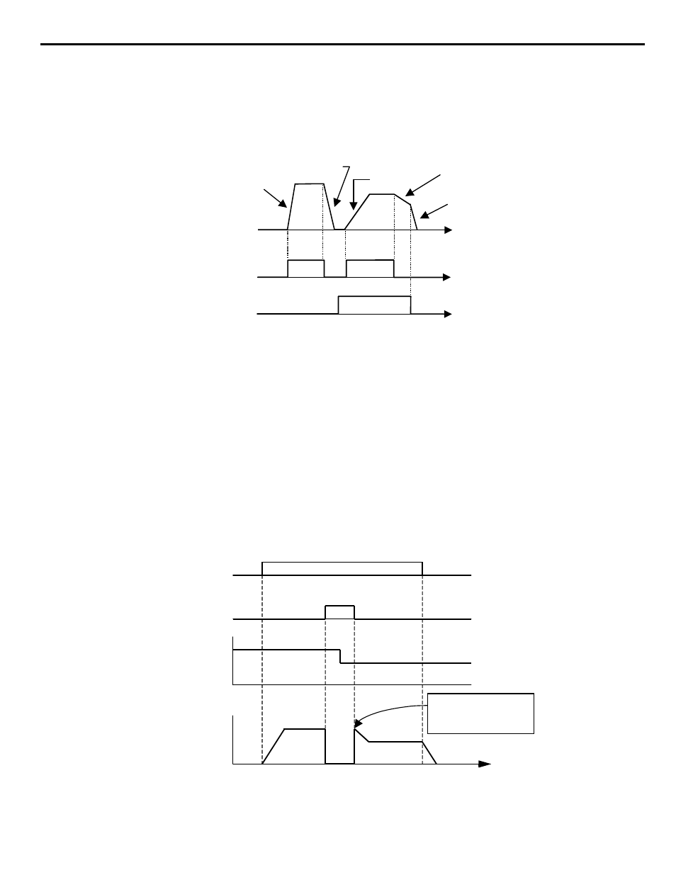
Function: Multi-Acc / Dec 1 (Setting: 7)
When a digital input configured as Multi-Acc/Dec 1 (H1-0x = 7) is OPEN the first set of acceleration / deceleration times (C1-01 and C1-
02) are active.
When a digital input configured as Multi-Acc / Dec 1 (H1-0x = 7) is CLOSED the second set of acceleration / deceleration times (C1-03
and C1-04) are active.
Figure 1.41
Figure 41. Multi-Accel/Decel Timing Diagram
■
Function: Ext Baseblk N.O. (Setting: 8)
■
Function: Ext Baseblk N.C. (Setting: 9)
When the iQpump drive is commanded into baseblock, gating of the output transistor stops and output voltage/frequency drops to zero
(motor coasts). The iQpump drive can be forced into a baseblock state by either closing a digital input configured for Ext Baseblk N.O.
(H1-0x = 8) or opening a digital input configured for Ext Baseblk N.C. (H1-0x = 9).
When the baseblock state is removed the speed search function is used to catch the coasting motor and ramp it back to the commanded
speed.
The method of speed search, Current Detection or Speed Estimation, that is utilized when the baseblock input is removed depends on the
setting of parameter b3-01:
If b3-01 = “0: SpdsrchF Disable” or “1: SpdsrchF Enable”; Speed Estimation is used
If b3-01 = “2: SpdsrchI Disable” or “3: SpdsrchF Enable”; Current Detection is used
Figure 1.42
Figure 42. External Baseblock Characteristics
(C1-01)
Decel Time 1
(C1-02)
Accel Time 2
(C1-03)
Decel Time 2
(C1-04)
Decel Time 1
(C1-02)
Output
Frequency
FWD (REV)
Run Command
Multi-Acc/Dec 1
Input
t
t
t
Accel Time 1
TIME
RUN Command
Baseblock Input
Speed Command
Output Frequency
Begin Speed Search
from stored Speed
Command
TIME