Yaskawa iQpump Controller Programming Manual User Manual
Page 144

144
YASKAWA
TM.iQp.07 iQpump Controller Programming Manual
◆
Function Description: MEMOBUS / Modbus Communication
When P1-01 = 3 (Pump Mode = MEMOBUS / Modbus Network), the drive will either become a Master or Slave, depending on P9-27
(Network Recovery). In addition, H5-01 (Serial Comm Address) is range limited by P9-25 (Highest Node Address). Setting P9-27 to
anything other than 0 (Automatic) will force that drive to never become a Master Network controller. When P9-27 = 0, the drive will
attempt to become a Master whenever P9-26 (Master Time-out) expires. A fixed amount of time (node address H5-01 x 0.25 s) is always
added to P9-26 to minimize network collision resulting from multiple drives attempting to become a master at the same time.
If P9-27 = 0 at start-up, the drive uses a different Master Time-out which is based on the node address:
Initial Master Time-Out (in seconds) = 1.5 + (node address H5-01 x 0.25)
If P9-27
≠
0, then P9-26 is used as the Master Time-Out at start-up.
So, if P9-27 = 0 for all the networked drives, logically when power is restored to the drives at the same time the drive with the lowest node
address will always become the Master drive initially (see
). Once a drive either becomes a master or receives data from it, the
start-up process is concluded and the drives use P9-26 plus a fixed number (node address H5-01 x 0.25 s) as the Master Time-out.
The drive that becomes a master during the start-up process will attempt to query the drives starting from address 1 up to P9-25 (Highest
Node Adr). If it gets a good response from the query, the drive gets added to the Network Active Pumps list. Drives in the Network Active
Pumps list are given network commands and refreshed regularly through the MEMOBUS / Modbus Sequencer.
Node addresses that are not part of the Network Active Pumps list, but are within the P9-25 range are queried regularly and added if they
become online. Nodes that are part of the Active list, but do not reply to the network commands are removed from the list.
In the event that the master goes down, another drive (P9-27 = 0) can assume master functionality after the Master Time-out expires. The
new master will use data from Pumps Available list to rebuild the network data. If the data suggests that there is an available drive on the
network, then the new master will not do a complete scan. It will also skip writing commands to the active drives until it performs a read
on the current Pump Status, which is then used to recreate the previous command given to that drive. However if the data suggests that
there no available drive, then it will do complete scan of all the valid node addresses.
A new master will perform Network Restore, which attempts to run the drives as they were before the old master went down by using the
drive’s current status. Additionally, if Network Restore encounters ambiguity, such as multiple lead drives running at the same time, it
will attempt to resolve the conflict following normal operation flow.
Setting P9-27 = 1 (Slave / Resume) prevents the drive from becoming a network master and at the same time will not cause a MSL fault
if the master does go down. It will continue running using the last command received.
Note: The drive will keep running in its current operation state which could cause an undesirable condition.
Setting P9-27 = 2 (Slave / Resume) prevents the drive from becoming a network master and at the same time will not cause a MSL fault
if the master does go down. It will continue running when the master is lost.
Setting P9-27 = 3 (Fault MSL) will fault the drive after P9-26 expires.
Parameter P9-28 (NETSCAN Alarm Time) can be varied to control the amount of time before a NETSCAN alarm is displayed after the
last time a message from the master has been received. High network latency or having a lot of offline drives will require a higher setting.
An offline drive is defined as a pump with node address within 1 to P9-25 that does not have power, has connection issues, or is
disconnected physically form the network.
More detailed information regarding functionality can be found in VSP130034-DD.
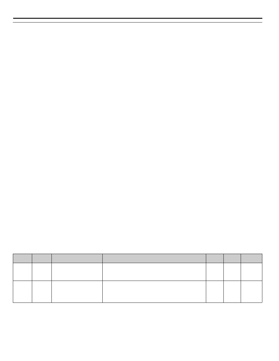
Table 46 Parameters
<0034>
Parameter
No.
Addr.
Hex
Parameter Name
Digital Operator Display
Description
Setting
Range
Factory
Setting
Menu
Location
H5-01
425
Drive Node Address
Serial Comm Adr
Selects drive station node number (address O for terminals R+, R-,
S+, and S- (drive power must be cycled before the changes will take
effect).
*Range is dependent on P9-25 if P1-01 = 3.
0 ~ 20*
1F
Programming
P1-01
600
Pump Mode
Pump Mode
Select type of control operation.
0 = Drive Only (Simplex)
1 = Drive + 1 Pump
2 = Drive + 2 Pumps
3 = MEMOBUS / Modbus Network
0 ~ 3
0
Programming