Function: speed search 1 (setting: 61), Function: speed search 2 (setting: 62), Function: speed search 3 (setting: 64) – Yaskawa iQpump Controller Programming Manual User Manual
Page 67: Function: comm test mode (setting: 67)
YASKAWA TM.iQp.07 iQpump Controller Programming Manual
67
■
Function: Speed Search 1 (Setting: 61)
■
Function: Speed Search 2 (Setting: 62)
■
Function: Speed Search 3 (Setting: 64)
Table 26 Digital Input Functions
The Speed Search function can be turned on for all starts with parameter b3-01. If, however, it is beneficial to only use Speed Search at
certain starts, a digital input can be programmed to turn on Speed Search only when it is closed.
Speed Search 1 will start searching for the rotor speed from the maximum frequency (E1-04). Speed Search 2 will begin searching for the
rotor speed from the existing Speed Command. Speed Search 3 will cause the motor to baseblock when the switch is open and then
perform Speed Search when it closes.
In all cases the form of Speed Search, Speed Estimation or Current Detection, is determined by the setting of b3-01. If b3-01 = “0:
SpdsrchF Disable,” then the Speed Estimation form of Speed Search is used. If b3-01 = “2: SpdsrchI Disable,” then the Current Detection
form of Speed Search is used.
■
Function: Comm Test Mode (Setting: 67)
The iQpump drive has a built-in function for self-diagnosing the serial communications operation. The test involves wiring the send and
receive terminals of the RS-485 / 422 port together. The iQpump drive transmits data and then confirms the communications are received
normally.
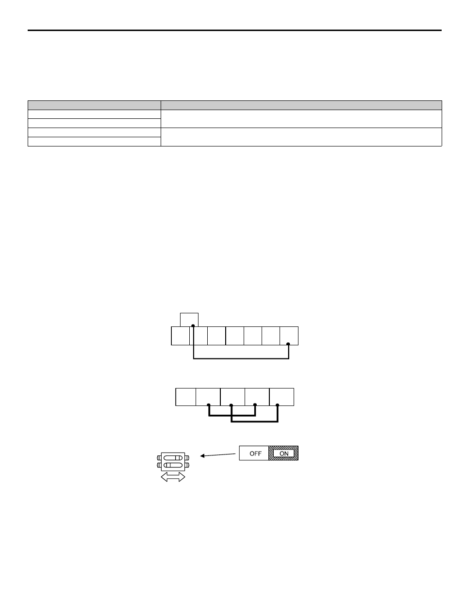
In order to perform the serial communications self-diagnosis, terminal S7 must be programmed as the Comm Test Mode digital input
(H1-05 = “67: Com Test Mode”) and then power removed from the iQpump drive and the following steps performed:
1. Wire the S7 and SC terminals of the control circuit terminals together
2. Wire the R+ and S+ terminals of the RS-485 / 422 port together
3. Wire the R- and S- terminals of the RS-485 / 422 port together
4. Turn On the terminating resistance (Move Switch 1 of Dip Switch 1 to the ON position).
Figure 1.48
Figure 48. DIP Switch Setting for Terminating Resistor
5. Turn on power to the drive.
After step 5 above the iQpump drive will either display “Pass” if everything is okay or a CE alarm will be displayed. If the CE alarm
occurs, the fault output contact will energize.
Setting of b3-01
Speed Search Method Used for Multi-function inputs
0
Speed Estimation
1
2
Current Detection
3
S1
S2
S3
S4
S5
S6
S7
SC
RP
R+
R-
S+
S-
S1
O
F
F
1
Terminating
resistance
DIP Switch S1 located on
removable terminal board.
2
1