Yaskawa iQpump Controller Programming Manual User Manual
Page 86
86
YASKAWA
TM.iQp.07 iQpump Controller Programming Manual
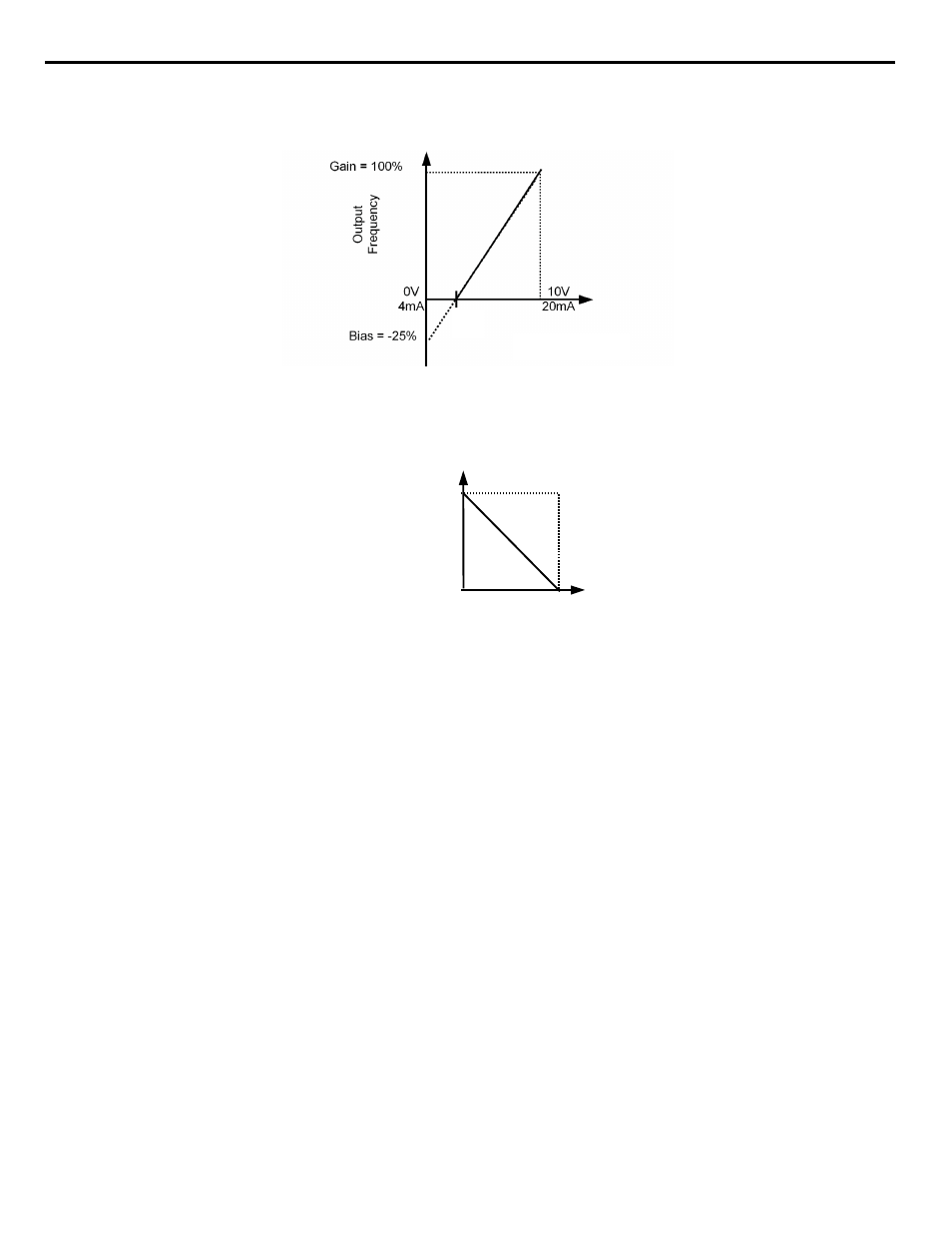
Adjustment of the bias setting will likewise adjust the speed command that is equivalent to the minimum analog input level (0 Vdc or 4
mA). If, for instance, the bias is set to –25%, then 0 Vdc or 4 mA will be equivalent to a –25% speed command. Since the minimum
speed command is 0% an analog input of 2 to 10 Vdc or 7.2 to 20 mA will now be equivalent to 0-100% speed command span.
Figure 1.74
Figure 74. Output Frequency with Reduced Bias Setting
As a further example, for an inverse-acting speed command, set the bias = 100% and the gain = 0%. The minimum analog input level (0
Vdc or 4 mA) will produce a 100% speed command and the maximum analog input level (10 Vdc or 20 mA) will produce a 0% speed
command.
Figure 1.75
Figure 75. Output Frequency with Inverted Gain and Bias Settings
2 V
7.2 mA
Analog Input Signal
20mA
4mA
0V
10V
Gain = 100%
Bias = 0%
Out
put
F
req
uen
cy
Analog Input Level
Analog Input Signal
Bias
Gain