Message format – Yaskawa iQpump Controller Programming Manual User Manual
Page 99
YASKAWA TM.iQp.07 iQpump Controller Programming Manual
99
MEMOBUS / Modbus communication can perform the following operations regardless of the settings in b1-01 and b1-02:
1. Monitoring operation status of the drive
2. Setting and reading iQpump drive parameters
3. Resetting faults
4. Input multi-function commands
Important:
An OR operation is performed between the multi-function command input from the PLC and the command input from multi-function
digital input terminals S3 to S7.
■
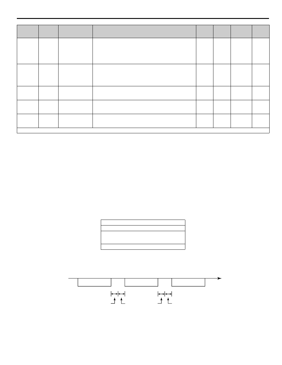
Message Format
In MEMOBUS / Modbus communication, the master sends commands to the slave, and the slave responds. The message format is
configured for both sending and receiving as shown below. The length of the data packets is changed by the command (function)
contents.
Figure 89. Message Format
The space between messages must support the following:
Figure 1.90
Figure 90. Message Spacing
Slave Address
Set the iQpump drive address from 0 to 32. If 0 is selected, commands from the master will be broadcast (i.e., the iQpump drive will not
return responses).
H5-04
0428
Stopping Method
after Communication
Error
Serial Fault Sel
Selects the stopping method when a communication error is
detected.
0: Ramp to Stop
1: Coast to Stop
2: Fast-Stop
3: Alarm Only
0 ~ 3
3
Programming
H5-05
0429
Communication
Error Detection
Selection
Serial Flt Dtct
Enables or disables the communications timeout detection function.
0: Disabled - A communications loss will NOT cause a
communications fault.
1: Enabled - If communications are lost for more than the time
specified in parameter H5-09, a communications fault will occur.
0 ~ 1
1
Programming
H5-06
042A
Drive Transmit Wait
Time
Transmit WaitTIM
Sets the time from when the drive receives data to when the drive
sends data.
5 ~ 65
5 ms
Programming
H5-07
042B
RTS Control
Selection
RTS Control Sel
Enables or disables “request to send” (RTS) control:
0: Disabled (RTS is always on)
1: Enabled (RTS turns on only when sending)
0 ~ 1
1
Programming
H5-09
0435
Communication
Error Detection Time
CE Detect Time
Determines how long communications must be lost before a fault is
annunciated. Works in conjunction with parameters H5-05 and
H5-04.
0 ~ 10.0
2.0 s
Programming
*Set H5-01 to 0 to disable drive responses to MEMOBUS / Modbus communications.
Slave address
Function code
Data
Error check
Parameter
No.
Addr. Hex
Parameter Name
Digital Operator
Display
Description
Setting
Range
Factory
Setting
Menu
Location
Page
Number
DDC to Drive
Drive to DDC
DDC to Drive
Command message
Response message
Command message
Time (Seconds)
24 bits long
5 ms min.
H5-06
setting
24 bits long