Yaskawa iQpump Controller Programming Manual User Manual
Page 230
230
YASKAWA
TM.iQp.07 iQpump Controller Programming Manual
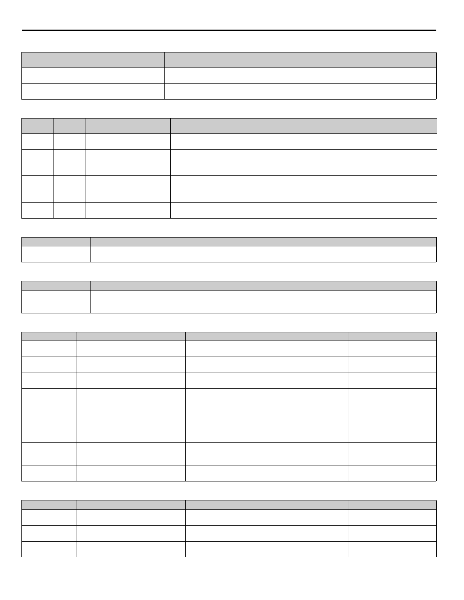
Table 103 Function Text
Table 104 Monitors
Table 105 Multi-Function Input Setting
Table 106 Multi-Function Output Setting
Table 107 Faults
Table 108 Alarms
Function Number
Function Name
Digital Operator Display
P6
Flow Meter Setup
Flow Meter Setup
P8
Pressure and Level Control
Pres&Lvl Control
Monitor
No.
Addr.
Hex
Monitor Name
Digital Operator Display
Description
U1-95
725
Flow Rate
Flow Rate
Displays the flow rate, based upon the voltage present on Terminal A1 and parameters P6-01 and P6-02. A
two second 1st order filter will be applied to this monitor.
U1-96
72A
Volume Accumulated (Fine)
Volume (Fine)
Displays the volume that has been measured by terminal A1. Total volume can be calculated as follows:
Total Volume = U1-97 * 1000 + U1-96.
Value retained in EEPROM.
U1-97
72B
Volume Accumulated (Course)
Volume (Course)
Displays the volume that has been measured by terminal A1. Total volume can be calculated as follows:
Total Volume = U1-97 * 1000 + U1-96.
Value retained in EEPROM.
U1-98
72C
Water Level
Water Level
Displays the amount of water above the water level sensor.
Setting
Description
75
Reset Accum
Closed: Volume accumulated will be reset to zero (and held at zero if digital input remains closed).
Setting
Description
57
Low Water Level
This will energize if the level in the well drops below the Low Level Detection Level (P8-07) for more than the Low Level Detection Delay
Time (P8-08), or if there is a LOWWL - Low Water Level Fault.
Fault Display
Description
Cause
Countermeasures
LOWFL
Low Flow
Low flow has been detected by the flow
meter.
Not enough flow, or incorrect “P6” settings
—
LOWWL
Low Water Level
Low Water Level
Water Level has gone below the P8-07 level for more than the P8-
08 time.
—
ACCUM
Accum Level
Accumulated Level
Accumulated level has exceeded the P6-09 and P6-10 settings.
Reset the accumulated level
(P6-03 or via digital input)
OPE13
Terminal A1
Programming error
Terminal A1 is being assigned to more than one of the following
functions.
- Frequency Reference (b1-01 = 1)
- Dual Zone PI is enabled (b5-01 = 2)
- Flow Meter Enabled (P6-01 > 0)
- Level Control Enabled (P8-01 =1)
- Hand Mode Ref Term A1 (P5-01 = 0)
Reprogram b1-01, b5-01, P6-01
or P8-01.
OPE14
FlowMtrNotEnable
Programming error
The sleep level type has been set to “FlowMtr-Term A1”
(P2-01 = 4) but the flow meter function is not enabled
(P6-01 = 0.0)
Reprogram P2-01 or P6-01.
HIFLO
High Flow
High flow has been detected by the flow
meter.
Too much flow or incorrect “P6” settings.
—
Alarm Display
Description
Cause
Countermeasures
LOWFL
Low Flow
Low flow has been detected by the flow
meter.
Not enough flow, or incorrect “P6” settings
—
LOWWL
Low Water Level
Water Level has gone below P8-07 level
for more than the P8-08 time.
ACCUM
Accum Level
Accumulated Level
Accumulated level has exceeded the P6-09 and P6-10 settings.
Reset the accumulated level
(P6-03 or via digital input)