Yaskawa p7, Function description, Figure 156. wiring diagram – Yaskawa iQpump Controller Programming Manual User Manual
Page 202
202
YASKAWA
TM.iQp.07 iQpump Controller Programming Manual
Figure 1.152
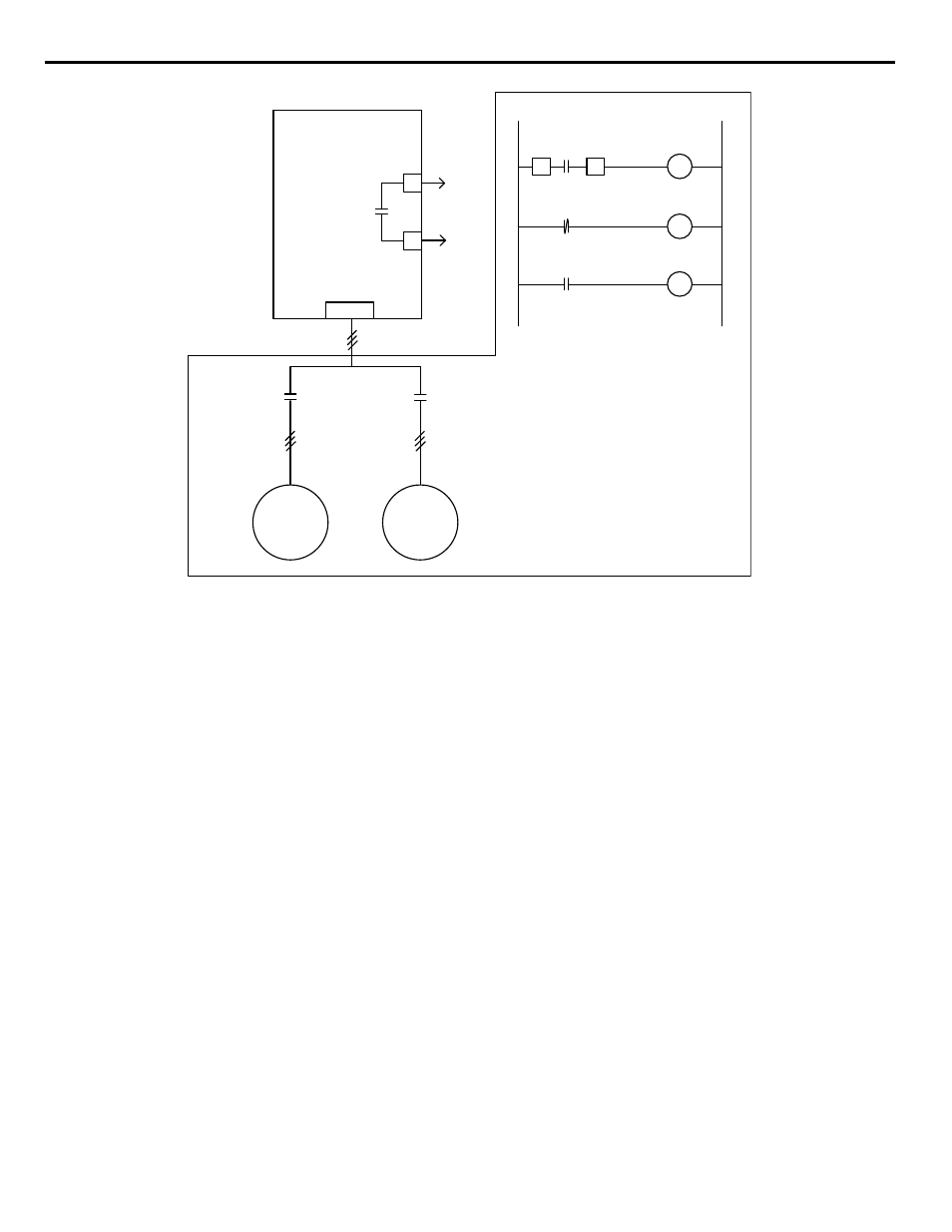
Figure 156. Wiring Diagram
■
Function Description:
<0034>
Two Motor Alternation Disabled (P4-14 = 0): When parameter P4-14 = 0, the 2-motor alternation function is disabled. All timers
associated with the 2-motor alternation function will be cleared. The digital output (H2-0x = 43) will be de-energized.
Two Motor Alternation Enabled (P4-14 = 1): When parameter P4-14 = 1, the 2-motor alternation function will be enabled. The drive
will first hold the “Mot 2 Alternate” digital output (H2-0x = 43) de-energized, which forces the relay / contactor logic to connect the first
motor to the drive's output terminals.
Any time the drive is putting power to the motor (running, non-zero speed, not base-blocked), the alternation timer will run. When the
timer reaches the time entered into the Alternation Time (P4-16) parameter, the drive will then switch over to the second motor,
depending on the setting of parameter P4-15. If P4-15 is set to “Wait For Stop” (P4-15 = 0), the drive will continue to operate on motor
1 until the drive would normally go to zero speed (zero reference, sleep mode, remove run command, fault). Once the drive comes to a
stop, the “Mot 2 Alternate” digital output (H2-0x = 43) will energize, so that when the drive restarts it will be running on motor 2.
If P4-15 is set to “Immediate” (P4-15 = 1) and the drive is operating in “Auto” mode when the alternation timer reaches the P4-16 level,
the drive will immediately stop using the selected stopping method (b1-03). Once the drive comes to a stop, the “Mot 2 Alternate” digital
output (H2-0x = 43) will energize, and the drive will restart and ramp back to speed after the minimum base-block time. However, if the
drive is operating in the “Hand” mode and the alternation timer reaches the P4-16 level, the drive will respond as if P4-15 is set to “Wait
For Stop”.
Once the digital output is switched so that motor 2 is being driven, the alternation timer re-starts. When enough time passes with the drive
running that the alternation timer reaches the P4-16 level, the drive will switch back to motor 1 similar to above, depending on the P4-15
setting.
The alternation timer and motor selection are stored to EEPROM once per hour. Whenever parameter P4-14 is changed, the internal
alternation timer and the alternation time stored in EEPROM are cleared.
P4-14 special considerations:
• When P4-14 is changed from 0 => 1 - Motor 1 will be used first.
• When P4-14 is changed from 2 => 1 - Motor 2will be used first.
• When P4-14 is changed from 3=> 1 - Motor 1 will be used first.
Yaskawa P7
M1
M2
CR1
Motor 1 / 2
K1
Motor 1
CR1
K2
Motor 2
CR1
L1
N
M1
M2
T1 T2 T3
Motor Leads
K1
Motor
1
K2
Motor
2
H2-0X = ??
Mot 2 Alternate
To relay
logic
Additional components
provided by customer