Yaskawa iQpump Controller Programming Manual User Manual
Page 279
YASKAWA TM.iQp.07 iQpump Controller Programming Manual
279
P1-09
0608
High Feedback Level
High FB Level
The drive will display a “High Feedback Level (HFB)” alarm when the
feedback level rises above the programmed level. The alarm will turn
off when the feedback level falls below the programmed High
Feedback Level minus the Hysteresis Level (P1-13). This function is
active during running in the hand mode, auto mode, pre-charge and
thrust-bearing mode.
If P1-01 = 3, parameter P9-18 uses this value to calculate the quick de-
stage feedback level.
<0034>
0.0 ~
6000.0
(system
units
P1-02)
155.0
(system
units
P1-02)
Programming
P1-10
0609
High Feedback Level
Fault Delay Time
Hgh Lvl Flt Time
The drive will initiate a “High Feedback Fault (HFB)” when the
feedback level rises above the programmed level for a time specified in
P1-10. The drive will coast to a stop when a fault occurs. This function
is active during running in all operation modes.
If P1-01 = 3, the function will stop all drives running on the network
when the system fault occurs.
<0034>
0 ~ 3600 s
2 s
Programming
P1-11
<0032>
0106
Maximum SetPoint
Difference
Max Set-point Diff
When the drive is running and the difference between the setpoint and
the feedback exceeds the level in P1-11 for the time specified in P1-12,
the drive will trip on a “Not Maintaining Set-point (NMS)”. The drive
will coast to a stop when a fault occurs. A value of 0 disables this
function. This function is only active during running while operating in
auto mode.
If P1-01 = 3, the function is active on the lead drive, but will stop all
drives running on the network when the system fault occurs.
<0034>
0.0 ~
6000.0
(system
units
P1-02)
0.0
(system
units
P1-02)
Programming
P1-12
<0032>
0107
Not Maintaining Set-
point Time
Not Maint SP Tm
Delay time before a Not Maintaining Set-point fault occurs. Pump
protection criteria specified in P1-11 must be met for the drive to fault.
The drive will coast to a stop when a fault occurs. A value of 0 disables
Not Maintaining Set-point fault.
0 ~ 3600 s
60 s
Programming
P1-13
0108
Hysteresis Level
Hysteresis Level
Hysteresis Level used for low and high feedback alarm detection. See
function P1-07 and P1-09.
0.0 ~ 100.0
(system
units
P1-02)
0.0
(system
units
P1-02)
Programming
P1-14
0109
Prime Loss Level
Prime Loss Level
Used to detect loss of prime in the pump. If output current drops below
this level for the time specified in P1-12 and the output frequency is at
fmax, a “Loss Of Prime” fault occurs. The drive will coast to a stop
when a fault occurs.
If P1-01 = 3, the function is active on the lead drive, but will stop all
drives running on the network when the system fault occurs.
<0034>
0.0 ~
1000.0 A
0.0 A
Programming
P1-15
010A
Low / Hi Water Digital
Input Configuration
Water DI Config
<0034>
Sets the type of control operation
0: Low N.O. - Hi N.O. (Low Water Normally Open, High Water
Normally Open)
<0034>
1: Low N.C. - Hi N.O. (Low Water Normally Closed, High Water
Normally Open)
<0034>
2: Low N.O. - Hi N.C. (Low Water Normally Open, High Water
Normally Closed)
<0034>
3: Low N.C. - Hi N.C.(Low Water Normally Closed, High Water
Normally Closed)
<0034>
To use the low water function one of the digital inputs (H1-XX=85)
needs to be programmed. The low water input can be used for a low
water condition or in combination with the pre-charge function to
indicate the reservoir is filled. The low water input fault is only active
during running while operating in auto mode.
0 ~ 3
0
Programming
P1-16
<0034>
87F
Loss of Prime Time
Prime Loss Time
Delay time before a Loss of Prime fault occurs. Pump protection
criteria specified P1-14 must be met for the drive to fault. On fault the
drive will coast to a stop.
1 ~ 600 s
20 s
Programming
Denotes that parameter can be changed when the drive is running.
Pump Protection
P2-01
060A
Sleep Level Type
Sleep Lvl Type
Sets the sleep type.
0: Output Frequency
1: Output Current
2: Feedback
3: Output Speed (rpm)
<0034>
4: Low Flow (Terminal A1 - Flow meter required)
<0034>
Note:
Feedback depends on PID direction operation.
Displays a “Sleep” Alarm when active.
0 ~ 4
0
Programming
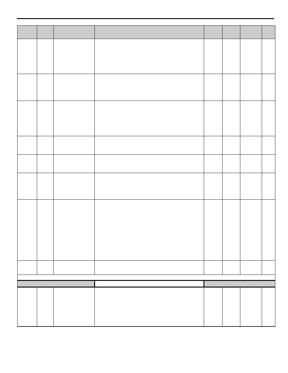
Parameter
No.
Addr.
Hex
Parameter Name
Digital Operator
Display
Description
Setting
Range
Factory
Setting
Menu
Location
Page
No.