Yaskawa iQpump Controller Programming Manual User Manual
Page 19
YASKAWA TM.iQp.07 iQpump Controller Programming Manual
19
Run / Stop Control:
• Only enabled when all three Run / Stop Control parameters are set to a value greater than zero (P4-18 > 0, P4-19 > 0, and P4-20 > 0).
• Available only when in HAND or LOCAL mode.
• PI control is disabled.
• Will always start off running when a run command is given.
• A stop command, power loss or fault will reset all timers and counters associated with the Run / Stop Control.
• A stop command will result in a stopping method set by parameter b1-03.
• When the “Run” portion of the timer expires, the drive stop using the stopping method set by parameter b1-03.
• When stopped due to the “Run” timer expired, the standard “sleep” message will be displayed on the operator.
• When stopped because the final cycle count has been exceeded, the digital operator will display “Run / Stop Finished”. The display
will be cleared when a stop command is given or power is lost.
• If a fault (not auto-restart) occurs during Run / Stop Control, all timers and counters are reset.
• If an auto-restart is in process, under most circumstances the Run / Stop Control will continue to operate. However, if the stop timer
expires prior to the auto-restart expiring, the drive will wait until the auto-restart time expires before resuming normal Run / Stop
Control.
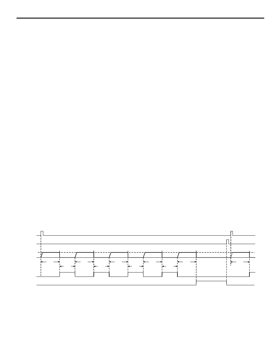
When this feature is enabled and the drive is given a run command, the drive will run for the time specified in parameter P4-18, then stop
for the time specified in parameter P4-19. It will do this the number of times programmed in parameter P4-20. (Refer to parameters P4-
18, P4-19 and P4-20.) The display will show one of two messages if the drive is stopped due to this feature. Run-Stop control cannot be
enabled when a multiplex mode (P1-01 > 0).
Timed Run:
If parameter b1-02 is set to 5 “Timed Run”, the timed run feature will be enabled. When “Timed Run” is enabled, Terminal S1 will be a
normally open “start” input and Terminal S2 will be a normally closed “stop” input. The drive can be started by either causing a rising
edge (open to close) on the S1 digital input when S2 is closed, or both S1 and S2 are closed when power is applied to the drive. The drive
will then start running at the HAND frequency reference P5-02 and run for the time specified in parameter P4-18. If the drive needs to be
stopped before the P4-18 timer expires, the circuit connected to Terminal S2 can be opened, or the Stop or Off keys on the digital operator
can stop the drive. The drive can be re-started by simply causing another rising edge on Terminal S1. There will be no modified display or
messages when the drive is stopped due to the Timed Run feature. If the drive is switched into HAND or LOCAL mode, the timed run
feature will be disabled.
1. Wire-Break detection for Terminal A2 will be completely disabled during Timed Run control.
2. The pre-charge feature is disabled during Timed Run control.
3. Uses the “Hand” reference as the frequency reference. If P5-01 is set to 1, parameter P5-02 will be used as the reference. If P5-02 is set
to 0, Terminal A1 will be used as the reference.
4. The “Not Maintaining Setpoint”, and “Low Feedback” faults are disabled during Timed Run control.
5. The “Loss of Prime” fault (if enabled) will become active when the output frequency comes to within 1 Hz of the frequency reference.
6. The Timed Run Control will take priority over the “Auto Mode Fixed Speed” mode (digital input).
When this feature is enabled, the drive will run at the “Hand” frequency reference for the time specified in parameter P4-18. Timed Run
cannot be enabled when in Multiplex Mode (P1-01 > 0). (Refer to parameter P4-18.)
Figure 1.9
Figure 9. Run / Stop Control - HOA Operator JVOP162 - Coast to Stop
“Hand”
Key
“Off”
Key
P4-18
R-S Run Time
P4-19
R-S Stop Time
P4-18
R-S Run Time
P4-19
R-S Stop Time
P4-18
R-S Run Time
P4-19
R-S Stop Time
P4-18
R-S Run Time
P4-19
R-S Stop Time
P4-18
R-S Run Time
Cycle
1
Cycle
2
Cycle
3
Cycle
4
Cycle
5
P4-18
R-S Run Time
Cycle
1
(Cycle 0)
Output
Frequency
P5-02
Sleep
Message
Run/Stop
Finished
Message
R-S Cycle Count
P4-20 = 5