Yaskawa iQpump Controller Programming Manual User Manual
Page 261
YASKAWA TM.iQp.07 iQpump Controller Programming Manual
261
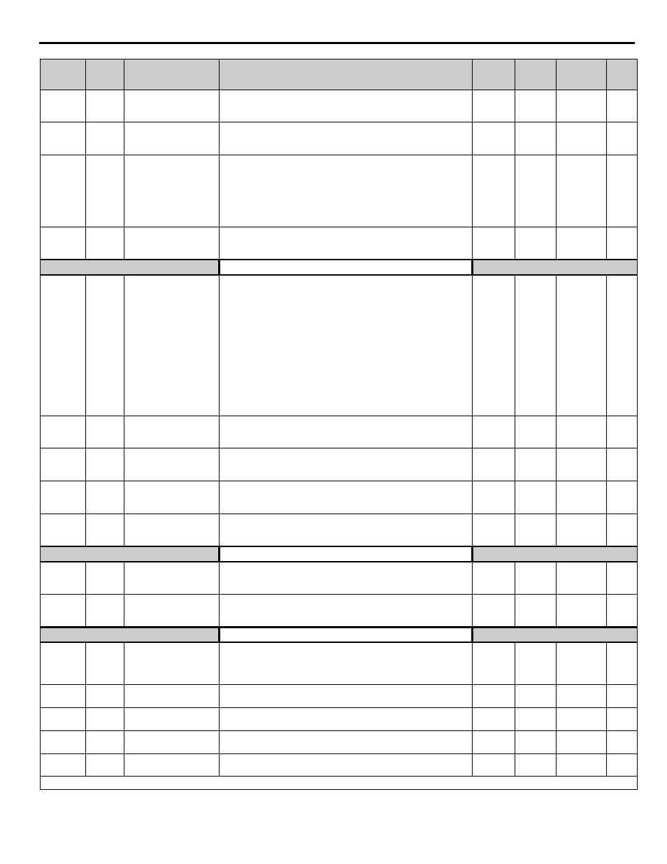
b2-02
018A
DC Injection Braking
Current
DCInj Current
Selects the DC injection braking current as a percentage of the drive
rated current.
0 ~ 100 %
50 %
Programming
b2-03
018B
DC Injection Braking
Time at Start
DCInj Time @ Start
Sets the time length of DC injection braking at start in units of 1
second.
0.00 to
10.00 s
0.00 s
Programming
b2-04
018C
DC Injection Braking
Time at Stop
DCInj Time @ Stop
When b1-03 = 2 actual DC Injection time is calculated as follows:
b2-04 x 10 x Output Frequency / E1-04. When b1-03 = 0, this
parameter determines the amount of time DC Injection is applied to the
motor at the end of the decel ramp. This should be set to a minimum of
0.50 seconds when using HSB. This will activate DC injection during
the final portion of HSB and help ensure that the motor stops
completely.
0.00 ~
10.00 s
0.5 s
Programming
b2-09
01E1
Motor Pre-Heat Current
Preheat Current
Motor Pre-heat current in % of drive rated current. This is used to keep
the motor warm to prevent condensation and is used in conjunction
with a digital input (data = 60).
0 ~ 100 %
0 %
Programming
Speed Search
b3-01
0191
Speed Search Selection
SpdSrch at Start
Enables / disables and selects the speed search function at start.
0: SpdsrchF Disable - Speed search at start is disabled (estimated speed
method is used at other times)
1: SpdsrchF Enable - Speed search is enabled (estimated speed
method)
2: SpdsrchI Disable - Speed search at start is disabled (current
detection method is used at other times)
3: SpdscrhI Enable - Speed search is enabled (current detection
method)
Estimated Speed Method: Actual motor speed and direction is
estimated, then the motor is ramped from that speed to the commanded
speed.
Current Detection Method: Current level is monitored while output
frequency is ramped down.
0 ~ 3
2
Programming
b3-02 0192
Speed Search
Deactivation Current
SpdSrch Current
Used only when b3-01 = 3. Sets the speed search operation current as a
percentage of drive rated current.
0 ~ 200 %
120 % Programming
b3-03
0193
Speed Search
Deceleration Time
SpdSrch Dec Time
Used only when b3-01 = 3. Sets the deceleration time during speed
search.
0.1 ~
10.0 s
2.0 s
Programming
b3-05
0195
Speed Search Delay
Time
Search Delay
Delays the speed search operation after a momentary power loss to
allow time for an external output contactor to re-energize.
0.0 ~
20.0 s
0.2 s
Programming
b3-14
019E
Bidirectional Speed
Search Selection
Bidir Search Sel
0: Disabled
1: Enabled
0 ~ 1
1
Programming
Delay Timers
b4-01
01A3
Timer Function ON-
Delay Time
Delay-ON Timer
Used in conjunction with a multi-function digital input and a multi-
function digital output. This sets the amount of time between when the
digital input is closed, and the digital output is energized.
0.0 ~
3000.0 s
0.0 s
Programming
b4-02
01A4
Timer Function OFF-
Delay Time
Delay-OFF Timer
Used in conjunction with a multi-function digital input and a multi-
function digital output. This sets the amount of time the output stays
energized after the digital input is opened.
0.0 ~
3000.0 s
0.0 s
Programming
PI Control
b5-01
01A5
PI Mode Setting
PI Mode
This parameter enable / disables the closed loop (PI) controller.
0: Disabled
1: Enabled (commanded speed becomes PI setpoint)
2: Enabled - 2 Zone (dual zone PI enabled)
<0034>
0 ~ 2
1
Programming
b5-02
01A6
Proportional Gain Setting
P Gain
Sets the proportional gain of the PI controller.
0.00 ~
25.00
2.00
Programming
b5-03
01A7
Integral Time Setting
PI I Time
Sets the integral time for the PI controller. A setting of zero disables
integral control.
0.0 ~
360.0 s
3.0 s
Programming
b5-04
01A8
Integral Limit Setting
PI I Limit
Sets the maximum output possible from the integrator. Set as a % of
fmax.
0.0 ~
100.0 %
100.0 % Programming
b5-06
01AA
PI Output Limit
PI Limit
Sets the maximum output possible from the entire PI controller. Set as
a % of fmax.
0.00 ~
100.00 %
100.00 % Programming
Denotes that parameter can be changed when the drive is running.
Parameter
No.
Addr.
Hex
Parameter Name
Digital Operator
Display
Description
Setting
Range
Factory
Setting
Menu
Location
Page
No.