3 standard aupc (automatic uplink power control), 4 doubletalk® carrier- in-carrier® (cnc), 5 data and miscellaneous interfaces – Comtech EF Data CDM-570A User Manual
Page 53
CDM-570A/570AL Satellite Modem with Optional Packet Processor
MN-CDM570A
Introduction
Revision 2
1–19
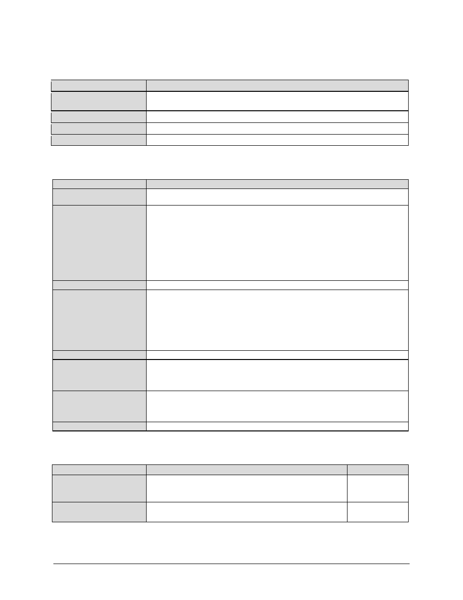
1.3.3 Standard AUPC (Automatic Uplink Power Control)
Parameter
Specification
Operating Mode
Requires Closed Network Framed mode for transport of Eb/No information from remote modem
(EDMAC can be enabled or disabled)
Target Eb/No Range
0 to 14.9 dB at remote demod (default is 4.0 dB)
Max AUPC Range
0 to 9 dB (default is 3 dB)
Monitor Functions
Remote demod Eb/No and Tx power level increase (front panel or via remote control interface)
1.3.4 DoubleTalk® Carrier- in-Carrier® (CnC)
Parameter
Specification
Operating Mode
Requires the two links to share a common carrier frequency (Outbound and Inbound symbol rates do not
have to be equal)
Power Spectral Density Ratio and
CnC Ratio
BSPK/QPSK/8PSK/8-QAM: –7 dB to +11 dB (ratio of power spectral density, outbound interferer to desired
inbound)
16-QAM: –7 dB to +7 dB (ratio of power spectral density, outbound interferer to desired inbound)
Note: With asymmetric carriers, the absolute power ratio (or CnC ratio) would be different, depending on the
ratio of the symbol rates.
Example:
Outbound interferer = 1 Msymbols/sec
Desired Inbound = 500 ksymbols/sec
Ratio of power spectral density = +7 dB
Absolute power ratio (CnC Ratio) = +7dB + (10
log
Outbound/desired symbol rate) = +10 dB
Maximum Symbol Rate Ratio
3:1 (TX:RX or RX:TX)
Inbound/Outbound frequency
uncertainty
Within the normal acquisition range of the demod, as follows:
CDM-570AL or CDMR-570AL (L-Band):
Below 64 ksymbols/sec: ±1 to ±(Rs/2) kHz, where Rs = symbol rate in ksymbols/sec
Between 64 and 625 ksymbols/sec: ±1 up to a maximum of ±32kHz.
Above 625 ksymbols/sec: ±1 to ±(0.1Rs) kHz, up to a maximum of ±200 kHz
CDM-570A (70/140 MHz):
Below 64 ksymbols/sec: ±1 to ±(Rs/2) kHz, where Rs = symbol rate in ksymbols/sec
Equal to 64 ksymbols/sec and above: ±1 up to a maximum of ±32kHz.
Delay range
0-330 ms
Eb/No Degradation
(equal Inbound/Outbound power
spectral density)
BPSK = 0.3dB QPSK = 0.3dB OQPSK = 0.3dB
8PSK = 0.5dB 8-QAM = 0.4dB 16-QAM = 0.6dB
For +10 dB power spectral density ratio (outbound interferer 10 dB higher than desired inbound) add an
additional 0.3 dB
Monitor Functions
Delay, in milliseconds
Frequency offset (between outbound interferer and desired inbound). 100 Hz resolution
CnC Power Ratio, in 0.1 dB (ratio of absolute power, outbound interferer to desired inbound)
Power Spectral Density Ratio, in 0.1 dB
CnC Monitor Accuracy
±0.2 dB for symmetric symbol rate
1.3.5 Data and Miscellaneous Interfaces
Connector
Function
Type
Primary Data
(3 selectable modes)
RS-422/EIA-530 DCE (Rates up to 10 Mbps) (also supports X.21 DCE & DTE)
V.35 DCE (Rates up to 10 Mbps)
Synchronous EIA-232 (Rates up to 300 kbps)
25-pin D-sub (female)
Optional G.703
1.544 Mbps T1 (Balanced 100Ω)
2.048 Mbps E1 (unbalanced 75Ω or balanced 120Ω)
15-pin D-sub (female)
or BNC (female)