2 terrestrial data connections group, 1 data interface connector, db-25f, The modem is always assumed to be dce – Comtech EF Data CDM-570A User Manual
Page 69
CDM-570A/570AL Satellite Modem with Optional Packet Processor
MN-CDM570A
Rear Panel Connectors and Pinouts
Revision 2
3–7
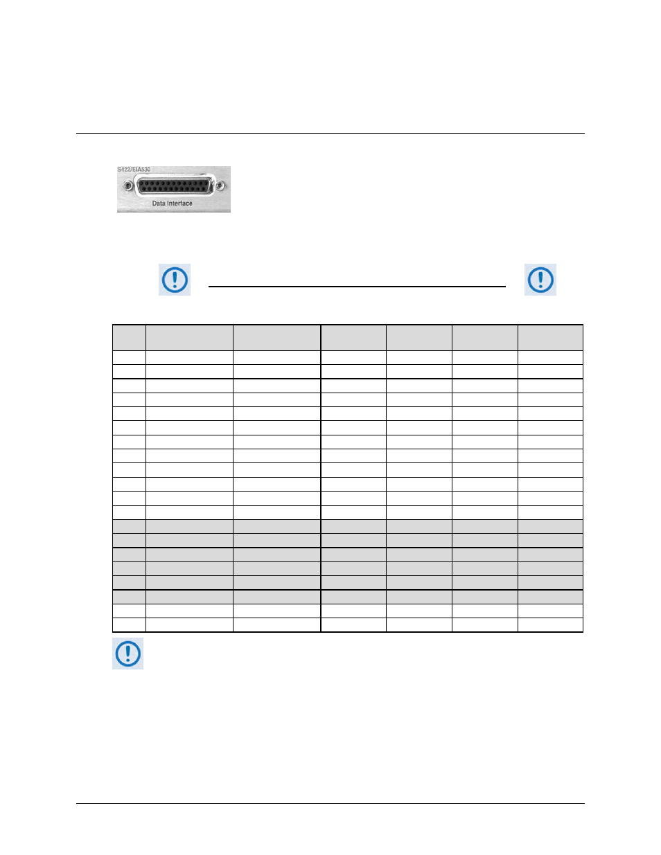
3.2.2 Terrestrial Data Connections Group
3.2.2.1 Data Interface Connector, DB-25F
This 25-pin ‘D’ type female (DB-25F) Data Interface connector
conducts data input and output breakout panel switching protection.
This connector conforms to the EIA-530 pinout, which allows for
connection of different electrical standards, including EIA-422, V.35,
and EIA-232. Shielded connectors resolve EMC problems unlike sometimes-used V.35
Winchester connectors.
THE MODEM IS ALWAYS ASSUMED TO BE DCE
Table 3-2. Data Interface Connector Pin Assignments
Pin #
Generic Signal
Description
Direction
EIA-422
EIA-530
V.35
EIA-232
Circuit #
2
Transmit Data A
DTE to Modem
SD A
SD A
BA
103
14
Transmit Data B
DTE to Modem
SD B
SD B
-
103
24
Transmit Clock A
DTE to Modem
TT A
SCTE A
DA
113
11
Transmit Clock B
DTE to Modem
TT B
SCTE B
-
113
15
Internal Tx Clock A
Modem to DTE
ST A
SCT A
DB
114
12
Internal Tx Clock B
Modem to DTE
ST B
SCT B
-
114
3
Receive Data A
Modem to DTE
RD A
RD A
BB
104
16
Receive Data B
Modem to DTE
RD B
RD B
-
104
17
Receive Clock A
Modem to DTE
RT A
SCR A
DD
115
9
Receive Clock B
Modem to DTE
RT B
SCR B
-
115
8
Receiver Ready A
Modem to DTE
RR A
RLSD
CF
109
10
Receiver Ready B
Modem to DTE
RR B
-
-
109
5
Clear to Send A *
Modem to DTE
CS A
CTS
CB
106
13
Clear to Send B *
Modem to DTE
CS B
-
-
106
4
Request to Send A *
DTE to Modem
RS A
RTS
CA
105
19
Request to Send B *
DTE to Modem
RS B
-
-
105
6
Data Set Ready A *
Modem to DTE
DM A
DSR
CC
107
22
Data Set Ready B *
Modem to DTE
DM B
-
-
107
7
Signal Ground
-
SG
SG
AB
102
1
Shield
-
Shield
FG
AN
101
1) This table is ordered by “Generic Signal Description” and not by connector pin orientation.
2) When the rear-panel switch marked “1:N Switch” is in the OFF position, all of the signals shown above
are available and functional. In addition, pins not shown are not connected, and therefore no damage
will occur if other signals are connected to the additional pins.
3) When the rear-panel switch marked “1:N Switch” is in the ON position, the highlighted signals, plus pins
18, 20, 21, 22, 23 and 25 are reserved for use by the 1:N system. DO NOT connect signals to any of
these pins in this mode. Certain pins have DC voltages present that may damage equipment other than
a Comtech EF Data redundancy switch.
4)
For X.21 operation, use the EIA-422 pins, but ignore Receive Clock if the Modem is DTE, and ignore
Transmit Clocks if the Modem is DCE.