G.6.3 the cnc automatic power control algorithm – Comtech EF Data CDM-570A User Manual
Page 538
CDM-570A/570AL Satellite Modem with Optional Packet Processor
MN-CDM570A
Appendix G
Revision 2
G–20
G.6.2 AUPC and Carrier-in-Carrier in the CDM-570A/AL
The CDM-570A/AL currently permits ‘classic’ AUPC when Carrier-in-Carrier mode is in operation,
but this does nothing to stop the problem of exceeding power limits when the fade is on the
‘wrong’ side. To limit the impact of this, you are constrained to 3 dB of permitted power
increase. Depending on the satellite band, and the depth and rapidity of the fade, this constraint
may curtail the effectiveness of the system.
G.6.3 The CnC Automatic Power Control Algorithm
In addressing the shortcomings of ‘classic’ AUPC, from its studies of the unique problems of
power control in CnC systems, Comtech EF Data has determined that there is sufficient
information available (CnC ratio, power level, Eb/No, RSL, etc.) on the local and distant sides to
control power at each end without exceeding the total composite power allocated to each
carrier in the CnC pair. Furthermore, the power control algorithm developed by Comtech EF
Data ensures that the CnC ratio remains within the correct working range.
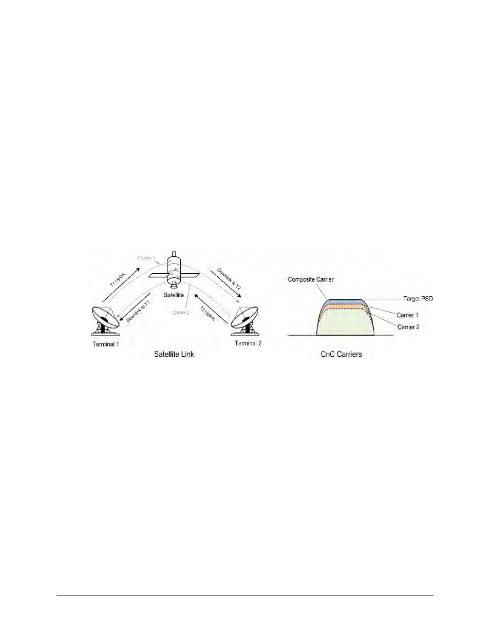
To recap, consider the following diagram:
Whenever you adjust power on Carrier 1, you need to adjust the power in Carrier 2 so the
composite carrier power remains constant (or does not exceed its allocated limit), while keeping
the CnC ratio within limits.
There are two distinct phases to the CnC-APC algorithm:
1) In order for the CnC-APC algorithm to work effectively, it must first analyze the CnC Ratio
and Eb/No margins on each side of the link, and based on the starting conditions, re-
distribute power between the two ends so that good protection against fades can be
achieved. This process is referred as re-balancing, and is done so that total composite power
(TCP) in the two carriers remains constant (within ±0.5 dB).
In this process, both sides of the link calculate power changes, based on their ability to see
not only local parameters, including CnC Ratio, Eb/No, Receive signal level, power level and
max power increase, but those of the modem at the other end of the link. After these
calculations are performed, a comparison of the results is performed, and if they are in close
agreement, the power changes are implemented.