G.4.5.4 commission and deploy carrier-in-carrier – Comtech EF Data CDM-570A User Manual
Page 532
CDM-570A/570AL Satellite Modem with Optional Packet Processor
MN-CDM570A
Appendix G
Revision 2
G–14
equivalent bandwidth when compared to the original side-by-side
8PSK, TPC 3/4 carriers:
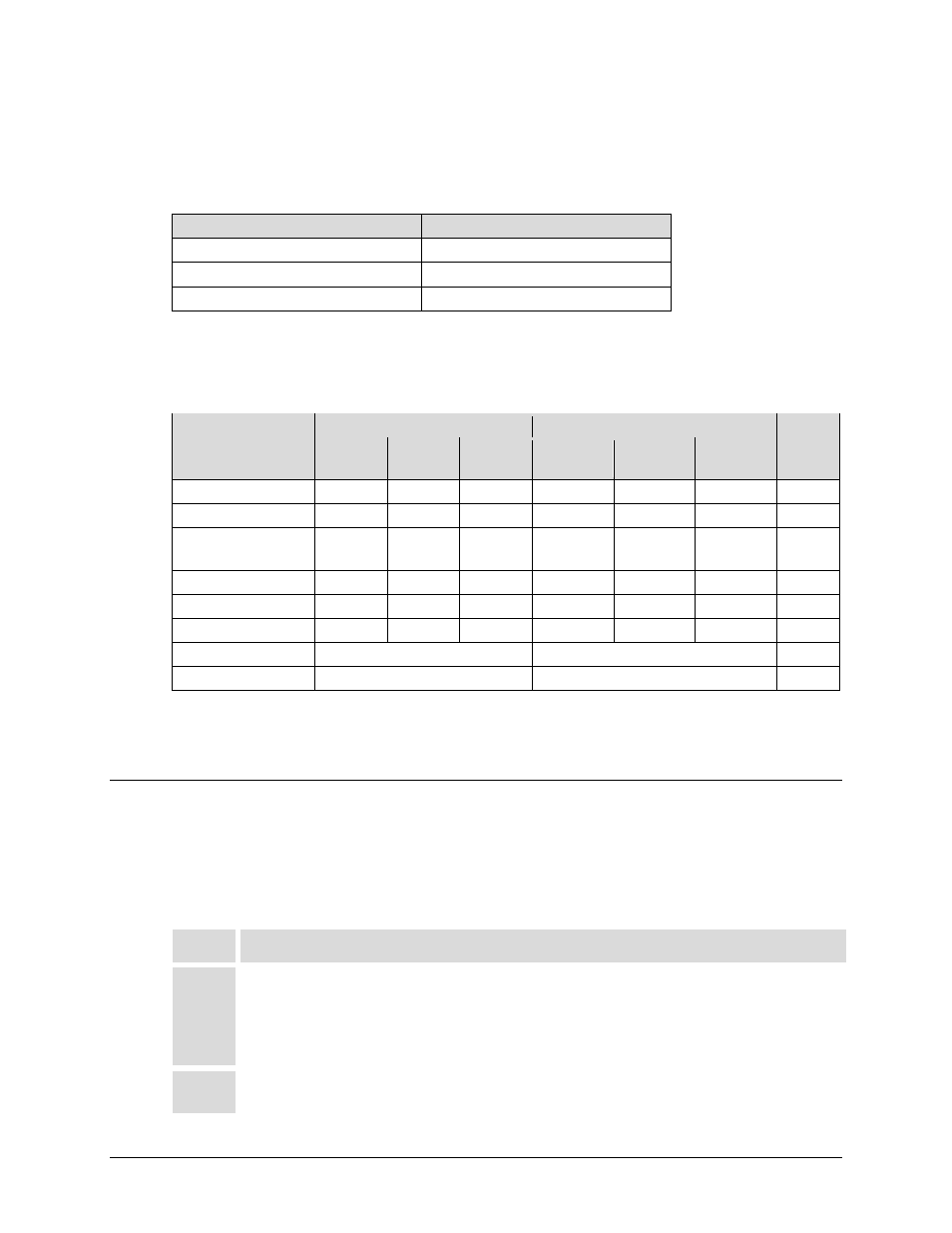
To continue, consider this example:
Satellite & Transponder
IS-901 @ 342º W, 22/22 (EH/EH)
Earth Station 1
Africa – 9.2 m
Earth Station 2
Africa – 4.5 m
Data Rate
2.048 Mbps / 2.048 Mbps
Whereas the original link used 8-PSK TPC 3/4, the Carrier-in-Carrier link used QPSK VersaFEC
0.803.
The savings summary is as follows:
Item
Original Link
With Carrier-in-Carrier and VersaFEC
Savings
Hub to
Remote
Remote
to Hub
Total
Hub to
Remote
Remote to
Hub
Total
Data Rate (kbps)
2048
2048
2048
2048
Modulation
8-PSK
8-PSK
QPSK
QPSK
FEC
TPC 3/4
TPC 3/4
VersaFEC
0.803
VersaFEC
0.803
Occupied BW (MHZ)
1.3
1.3
2.6
1.8
1.8
1.8
Power Eq. BW (MHz)
2.2
1.0
3.2
1.1
0.5
1.6
Leased BW (MHz)
3.2
1.8
44%
Hub BUC (W)
5
2
60%
Remote BUC (W)
20
5
75%
Using Carrier-in-Carrier and VersaFEC reduced the leased bandwidth by almost 44% and the BUC
size by 60% at the Hub and 75% at the Remote.
G.4.5.4 Commission and Deploy Carrier-in-Carrier
Prior to commissioning a Carrier-in-Carrier link, it is critical that the link is fully tested in non
Carrier-in-Carrier mode and all system issues including external interference, antenna pointing,
cabling, SSPA backoff are resolved. Only after the link is robust, should you attempt turning on
Carrier-in-Carrier. The following steps are recommended for Carrier-in-Carrier commissioning
and deployment:
Step
Task
1
Turn ON the carrier at Site A. Carrier from Site B is OFF. CnC function is OFF at both sites.
Using a spectrum analyzer, measure Co+No/No at the input to the modem at Site A.
Using a spectrum analyzer, measure Co+No/No at the input to the modem at Site B.
Measure/record Eb/No at Site B. Make sure there is sufficient margin to account for CnC.
Measure/record Receive Signal Level (RSL) at Site B.
2
Turn OFF the carrier at Site A. Turn ON the carrier at Site B. CnC function is OFF at both sites.
Using a spectrum analyzer, measure Co+No/No at the input to the modem at Site A.