4 1:1 control connector, db-9f – Comtech EF Data CDM-570A User Manual
Page 74
CDM-570A/570AL Satellite Modem with Optional Packet Processor
MN-CDM570A
Rear Panel Connectors and Pinouts
Revision 2
3–12
•
A pin that can mute the transmit carrier; this requires that the pin be shorted to ground or a
TTL ‘low’, or that an EIA-232 ‘high’ signal be applied.
•
An analog AGC signal (Pin 2) as an aid to antenna pointing or for driving step-track
equipment.
Table 3-6. Alarms Connector Pin Assignments
Pin # Signal Function
Name
1 Ground
GND
9
EXT Carrier OFF
EXT-OFF
2 AGC Voltage (Rx signal level, 0 to 10 volts)
AGC
10
No Connection
N/C
3 Rx Q Channel (Constellation monitor)
RX-Q
11
Rx I Channel (Constellation monitor)
RX-I
4 Unit Fault
UNIT-COM
12
Unit Fault (Energized, No Fault)
UNIT-NO
5 Unit Fault (De-energized, Faulted)
UNIT-NC
13
Tx Traffic
TX-COM
6 Tx Traffic (Energized, No Fault)
TX-NO
14
Tx Traffic (De-energized, Faulted)
TX-NC
7 Rx Traffic
RX-COM
15
Rx Traffic (Energized, No Fault)
RX-NO
8 Rx Traffic (De-energized, Faulted)
RX-NC
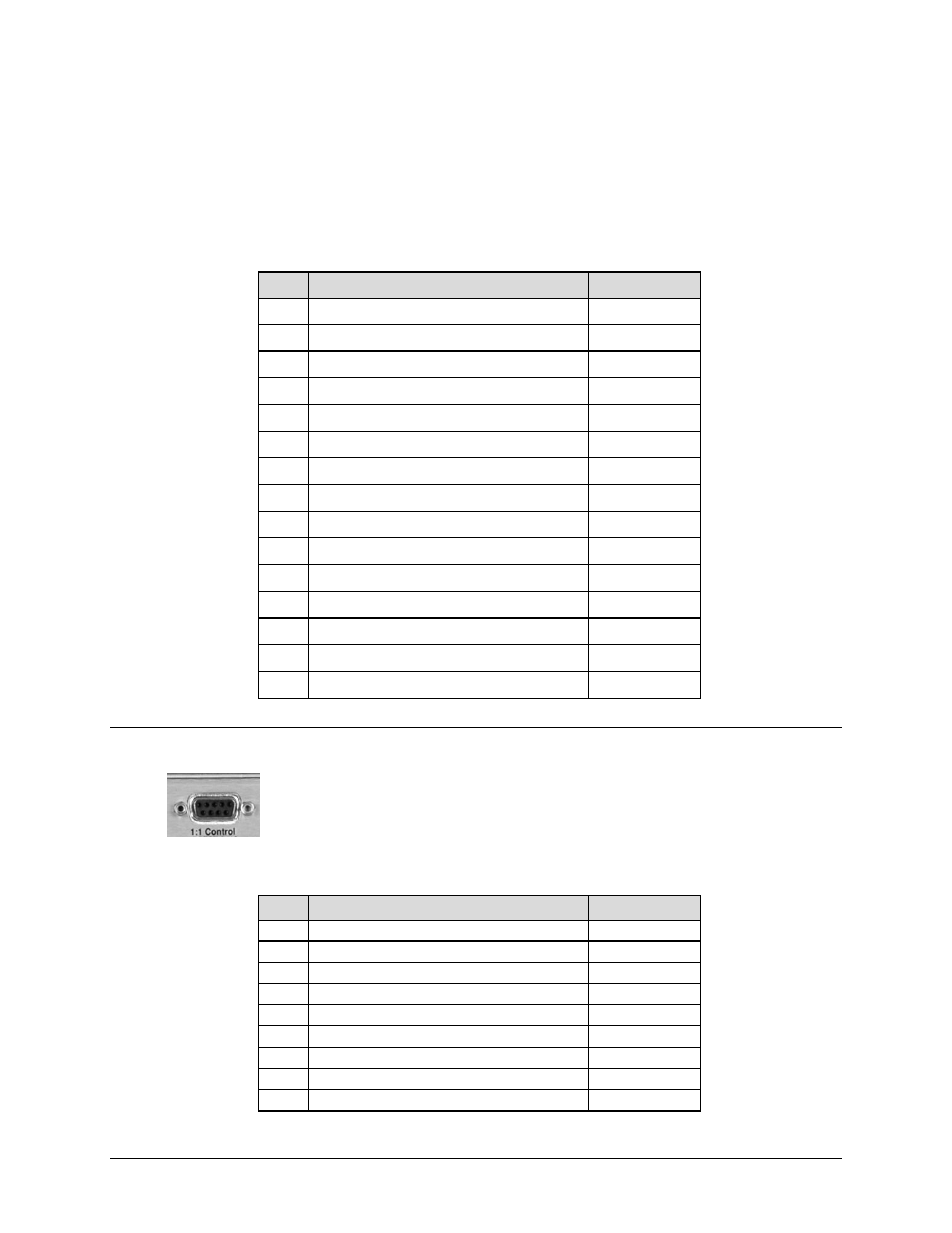
3.2.3.4 1:1 Control Connector, DB-9F
Use this
9-pin type ‘D’ female connector (DB-9F) to connect the modem only to
a CRS-170A (L-Band) or CRS-180 (70/140 MHz) switch in 1:1 redundancy
configurations.
Table 3-7. 1:1 Control Connector Pin Assignments
Pin # Description
Direction
5 Ground
---
9
Fused +12 volt
Out
4 Redundancy In 2
In
8
Redundancy Out 2
Out
3 Redundancy In 1
In
7
Redundancy Out 1
Out
2 Receive Serial Data – auxiliary channel
In
6
Transmit Serial Data – auxiliary channel
Out
1 Ground
---