Yaskawa VS-626 MC5 User Manual
Page 108
6.1
Common Settings
- 5
D
Settings
Setting
Function
0
0 to 10 VDC input [10--bit input]
1
--10 to 10 VDC input
(A negative voltage is a reference for reverse rotation.)
2
4 to 20 mA input
D
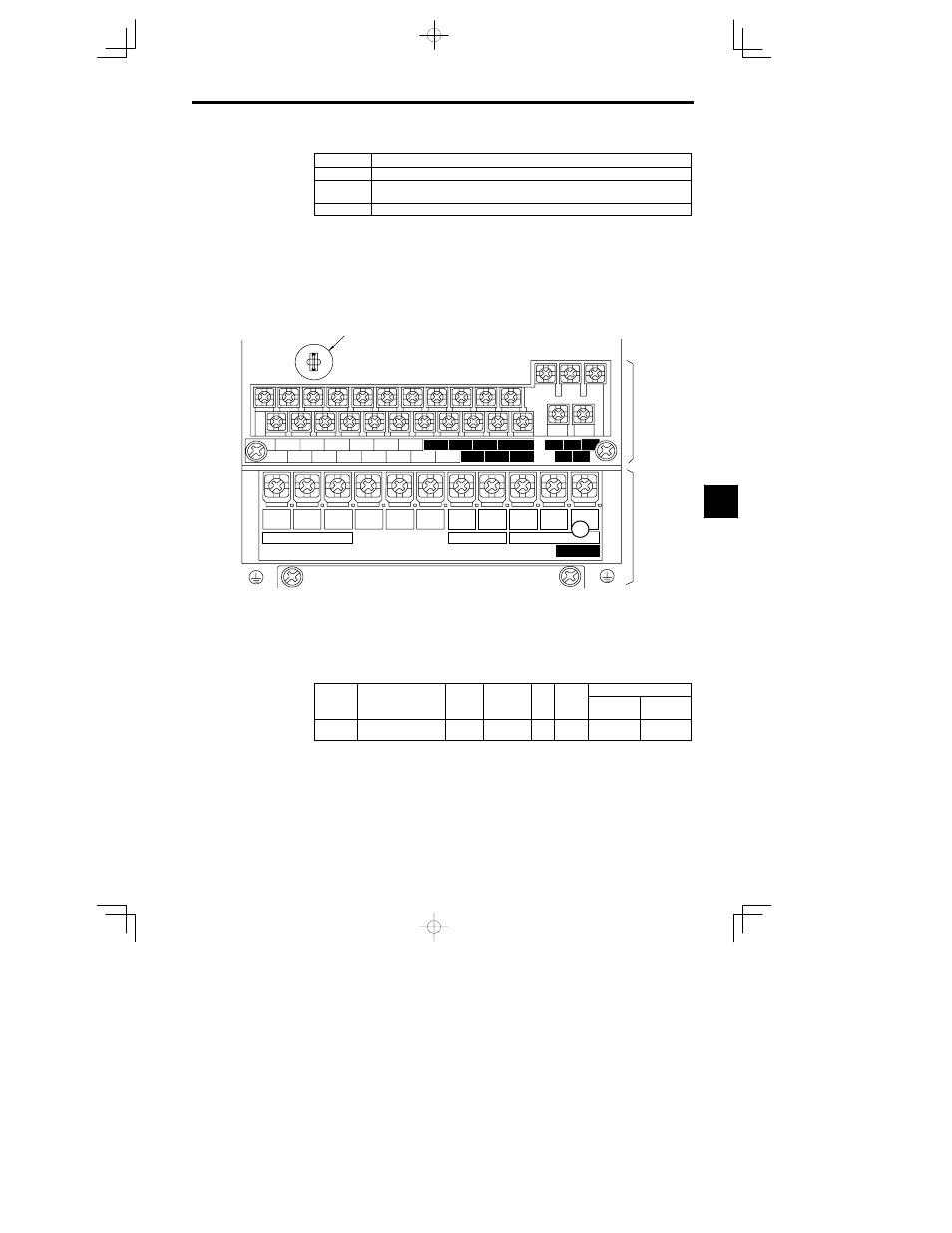
When the terminal is being used as a voltage input terminal (setting 0 or 1), jumper J1 must be discon-
nected on the control board. (See Figure 6.1.) The terminal’s input resistor will be destroyed if the ter-
minal is used for a voltage input with jumper J1 connected.
D
When frequency references are being input simultaneously from both the voltage terminal 13 and the
current terminal 14, the final reference value will be the sum of the two references that are input.
D
To switch the frequency reference input between the voltage terminal 13 and the current terminal 14,
set a value of 1F in any one of the multi-function inputs (H1-01 through H1-06).
The voltage terminal 13 will be used when this multi-function input is OFF and the current terminal
14 will be used when this multi-function input is ON.
D
If a 0 to
r10 VDC input is set, H3-01 must also be set to a 0 to r10 VDC input.
Jumper wire
Control circuit
terminals
Main circuit
terminals
10
B2
V
T2
Power input
Braking Resistor
Motor output
CHARGE
J1
1
2
3
4
5
6
7
8
21
22
23
9
11 12
(
G
)
13
14
15
16
17
25
26
27
33
18
19
20
R
L1
S
L2
T
L3
©
¨
1
¨
2
B1
W/T3
U
T1
Fig
6.1
Terminal Arrangement of a 200 V Class Inverter of 0.4 kW
J
Function and Signal Level for Multi-function Analog Input (Terminal 16):
H3-04, H3-05
D
This function is useful when switching between two analog inputs. The input is from terminal 16.
D
When using the multi-function input (terminal 16) as the frequency reference terminal, first set the
multi-function analog input function to “Auxiliary Reference” by setting constant H3-05 to 0.
Function for Multi-function Analog Input, Terminal 16: H3-05
User
Change
during
Setting
Factory
Valid Access Levels
User
Constant
Number
Name
during
Opera-
tion
Setting
Range
Unit
Factory
Setting
Open Loop
Vector
Flux Vector
H3-05
Multi-function analog
input (terminal 16)
0 to 1F
--
0
B
B
D
The auxiliary reference is factory-preset to 0.
D
After setting H3-05 to 0, set any one of the multi-function inputs (H1-01 through H1-06) to a value
of 3 (multi-step speed reference 1).
D
When a multi-function analog input has been set to “Auxiliary Reference,” it is treated as frequency
reference 2 during multi-step speed operation, so it can’t be used unless the multi-step speed reference
1 has been set.
6