Yaskawa VS-626 MC5 User Manual
Page 237
8.2
Programming Mode Constants
- 29
J
Torque Limit: L7
Consta
nt
Name
Set-
Facto-
Change
during
Control Modes
nt
Num-
ber
Display
Description
Set
ting
Range
Facto
ry Set-
ting
g
during
Opera-
tion
Open Loop
Vector
Flux Vector
Page
L7-01
Forward torque
limit
0 to
300
200
B
B
- 3
11
L7 01
Torq Limit Fwd
Sets the torque limit value as a percentage
f h
d
300
200
B
B
- 11
L7-02
Reverse torque
limit
Sets the torque limit value as a percentage
of the motor rated torque.
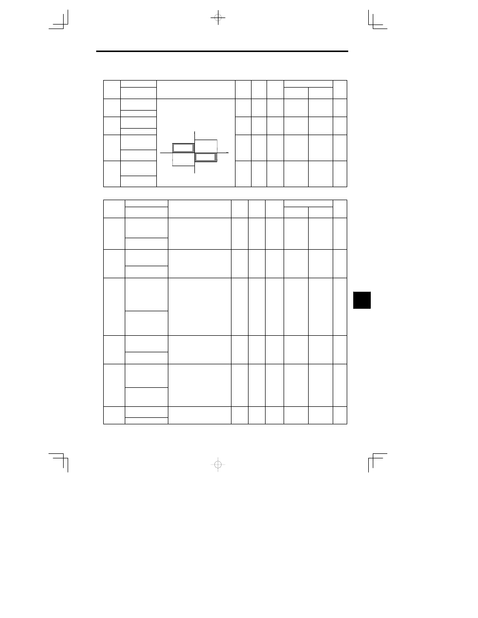
Four individual regions can be set.
Output torque
0 to
300
200
B
B
- 3
11
L7 02
Torq Limit Rev
Output torque
Forward side
300
200
B
B
- 11
L7-03
Forward regen-
erative torque
limit
Forward side
L7-01
L7-04
Motor
speed
Regenera-
tive state
0 to
300
200
B
B
- 3
11
L7 03
Torq Lmt Fwd
Rgn
Reverse
speed
tive state
Regenera-
tive state
300
200
B
B
- 11
L7-04
Reverse regen-
erative torque
limit
L7-02
Reverse side
L7-03
Forwa
tive state
0 to
300
200
B
B
- 3
11
L7 04
Torq Lmt Rev
Rgn
300
200
B
B
- 11
J
Hardware Protection: L8
Constant
Name
Setting
Factory
Change
during
Control Methods
Constant
Number
Display
Description
Setting
Range
Factory
Setting
g
during
Opera-
tion
Open Loop
Vector
Flux Vector
Page
L8-01
Protect selection for
internal DB resistor
(Type ERF)
0: Disabled (no overheating
protection)
1: Enabled (overheating protec-
tion)
0 to 3
0
B
B
- 57
DB Resistor Prot
)
2: 3%ED
3: 10%ED
L8-02
Overheat pre-alarm
level
Sets the detection temperature for
the Inverter overheat detection pre-
alarm in
qC.
The pre alarm detects when the
50 to
110
95
A
A
- 58
L8 02
OH Pre-Alarm Lvl
The pre-alarm detects when the
cooling fin temperature reaches
the set value.
110
95
A
A
- 58
L8-03
Operation selection
after overheat pre-
alarm
Sets the operation for when the In-
verter overheat pre-alarm goes ON.
0: Ramp to stop in deceleration
time C1-02.
1: Coast to stop
2: Fast stop in fast-stop time
C1-09.
0 to 3
3
A
A
- 58
OH Pre-Alarm Sel
C1-09.
3: Continue operation (Monitor
display only.)
A fault will be given in setting 0
to 2 and a minor fault will be
given in setting 3.
L8-05
Input open-phase
protection selection
0: Disabled
1: Enabled (Detects if input cur-
rent open-phase, power supply
voltage imbalance or main cir
0 1
0
A
A
- 58
L8 05
Ph Loss In Sel
p
p
p
pp y
voltage imbalance or main cir-
cuit electrostatic capacitor dete-
rioration occurs.)
0 1
0
A
A
- 58
L8-07
Output open-phase
protection selection
0: Disabled
1: Enabled (Output open-phase de-
tected at less than 5% of Invert-
er rated current.)
Output open-phase may be de-
0 1
0
A
A
- 58
L8 07
Ph Loss Out Sel
Output open-phase may be de-
tected inadvertently when ap-
plied motor capacity is small for
Inverter capacity. In this case, set
to 0 (Disabled.)
0 1
0
A
A
- 58
L8-10
Ground protection
selection
0: Disabled
1: Enabled
0 1
1
A
A
----
L8 10
Gnd Det Sel
1: Enabled
0 1
1
A
A
----
8