Yaskawa VS-626 MC5 User Manual
Page 186
Advanced Operation
7.3.6 Protective Functions: L
- 48
7.3.6 Protective Functions: L
J
Motor Protection Settings: L1-01, L1-02
Motor Protection Selection: L1-01
User
Change
during
Setting
Factory
Valid Access Levels
User
Constant
Number
Name
during
Opera-
tion
Setting
Range
Unit
Factory
Setting
Open Loop
Vector
Flux Vector
L1-01
Motor protection selec-
tion
0 1
--
1
B
B
D
Settings
Setting
Function
0
Disabled.
1
Enabled.
D
This setting enables or disables the motor overload protection function.
D
The rated current setting (E2-01) is used as a basis for overload detection.
D
Disable the motor protection function (setting 0) when two or more motors are connected to a single
Inverter. Use another method to provide overload protection separately to each motor, such as connect-
ing a thermal overload relay to the power line of each motor.
D
The motor protection function may not protect a motor when the power supply is turned ON and OFF
frequently, because the thermal value is reset each time that the power is turned OFF.
D
If the Overload OL1 alarm (1F) is set in one of the multi-function outputs (H2-01 to H2-03), the output
will be turned ON when the electronic thermal value reaches 90% of the overload detection level.
Motor Protection Time Constant: L1-02
User
Change
during
Setting
Factory
Valid Access Levels
User
Constant
Number
Name
during
Opera-
tion
Setting
Range
Unit
Factory
Setting
Open Loop
Vector
Flux Vector
L1-02
Motor protection time
constant
0.1 to 5.0
Min-
utes
1.0
B
B
D
Normally it isn’t necessary to change this setting. (The factory setting is a 150%, 1 minute capacity.)
D
Set the electronic thermal protection operation time if a 150% overload is applied after operating con-
tinuously at the motor’s rated current (hot start).
D
When the motor’s overload capacity level is known, set the hot-start overload resistance level for the
motor, but be sure to allow some margin for safety.
D
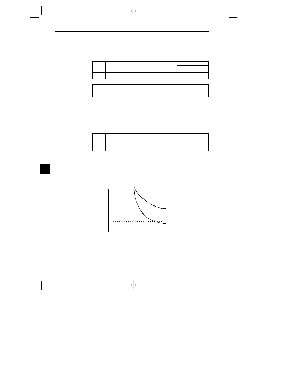
Decrease this setting when you want to detect an overload more quickly.
Operating time (minutes)
10
7
3
1
0.4
0.1
0
100
150
200
Cold start
Hot start
Motor current (%)
(E2-01 is 100%.)
Electronic Thermal Time Characteristics
In this example, L1-02 is set to 1 minute, the motor is operating at 60 Hz, and general-purpose
motor characteristics are used.
Fig
7.29
Motor Protection Operating Time
7