Yaskawa VS-626 MC5 User Manual
Page 170
Advanced Operation
7.3.5 External Terminal Functions: H
- 32
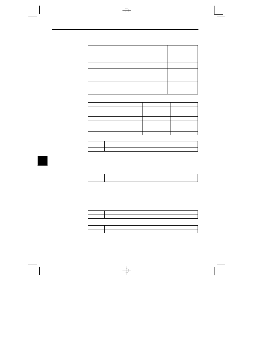
Constant Settings
User
Change
during
Setting
Factory
Valid Access Levels
User
Constant
Number
Name
during
Opera-
tion
Setting
Range
Unit
Factory
Setting
Open Loop
Vector
Flux Vector
H1-01
Multi-function input 1
(terminal 3)
0 to 77
--
24
B
B
H1-02
Multi-function input 2
(terminal 4)
0 to 77
--
14
B
B
H1-03
Multi-function input 3
(terminal 5)
0 to 77
--
3 (0)
B
B
H1-04
Multi-function input 4
(terminal 6)
0 to 77
--
4 (3)
B
B
H1-05
Multi-function input 5
(terminal 7)
0 to 77
--
6 (4)
B
B
H1-06
Multi-function input 5
(terminal 8)
0 to 77
--
8 (6)
B
B
D
The factory settings in parentheses are for when the Unit is initialized for 3-wire control.
D
The following table shows the settings and section references for some common functions.
Function
Setting
Section
3-wire sequence (forward/reverse run command)
0
6.1.8
Multi-step speed references 1 to 3 and jog fre-
quency reference
3 to 6
6.1.8
Accel/Decel time 1 and 2
7 1A
6.1.8
Emergency stop
15
6.1.8
FJOG/RJOG commands
12 13
6.1.8
Terminal 13/14 switch
1F
6.1.8
Timer function input
18
7.3.1
Local/Remote Selection (Setting: 1)
OFF
Operate with the frequency reference and run command specified in b1-01 (the frequency refer-
ence source) and b1-02 (run source).
ON
Operate with the frequency reference and run command set at the Digital Operator.
D
With this setting, the multi-function input selects the input method for the frequency reference and run
command.
D
The input method can be switched only when the Inverter is stopped.
D
The Digital Operator LOCAL/REMOTE Key is disabled when this function has been set in a multi-
function input.
Option Card/Inverter Selection (Setting: 2)
OFF
The Inverter frequency reference is enabled.
ON
The Option Card frequency reference is enabled.
D
With this setting, the multi-function input enables the frequency reference input from the Inverter itself
or the one from Option Card. The frequency reference input can be switched only when the Inverter
is stopped.
D
Be sure that b1-01 (the frequency reference source selector) has been set to 0 (Operator) or 1 (external
terminal). Only the frequency reference from the Option Card will be enabled if b1-01 is set to 3 (Op-
tion PCB).
D
Setting 2 can’t be selected if the AI-14B is being used and constant F2-01 (AI-14 Input Selector) is
set to 0.
External Baseblock NO (Setting: 8)
OFF
Normal operation
ON
Baseblock
External Baseblock NC (Setting: 9)
OFF
Baseblock
ON
Normal operation
D
With either of these settings, the multi-function input controls baseblock operation.
D
Baseblock is an interruption of the Inverter output. The motor coasts while the baseblock command
is being input.
7